


Features
Applications
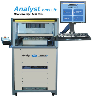
Analyst ems+ft In Circuit Test Overview
The CheckSum Analyst ems+ft extends the testing power of the Analyst ems with an integrated functional test subsystem that includes flexible stimulus, measurement and switching capabilities. It combines in circuit test (ICT) with power-up functional test to provide high fault coverage in a single, low-cost platform that can be customized by the user to fit a variety of test requirements.ÂÂÂ
Including industry-unique features such as 250VAC switching and a fully integrated DMM, function generator and counter-timer, as well as available relay switching in 50 point increments, the Analyst ems+ft meets a broad range of functional test requirements from straightforward power up „board alive” tests to extensive functional test sequences.
A typical test sequence on the Analyst ems+ft would proceed as follows:
Solid-state switching in 200-point increments and 50-point relay switch matrix cards may be mixed in any combination.
Circuits with voltages up to about ±12V will typically employ solid-state switching and voltages up to 250Vp-p are accommodated by relay switching. When greater than 40 volts is present at the UUT during test, the test fixture should be designed with safety shielding and operator interlocks to help prevent the operator from coming in contact with the signals.
In most cases functional test can be performed using the same test fixture as the in circuit test so that minimal time is spent transferring, loading and unloading the UUT.
The Analyst ems+ft includes an additional 19 inch rack space, allowing addition of off-the-shelf measurement/stimulus instruments or programmable power supplies to meet special requirements.
Functional Test Capabilities
The CheckSum FUNC-2 board is at the heart of the Analyst ems+ft system and provides the capabilities used for a wide range of functional testing requirements:
For unique or more sophisticated functional testing needs, the System can control GPIB instrumentation via an IEEE-488 controller.
Analog Measurements
DC Volts
The system can measure up to 250VDC. Measurements are made in a fully differential input mode up to 250V. Ranges include 0.2V, 0.6V, 2V, 6V, 10V, 20V, 60V, 200V and 600V (rated to 250V) and auto-range.
AC Volts
The system can measure up to 250VRMS. These true RMS measurements are provided with AC or AC+DC coupling. Ranges include 0.2V, 0.6V, 2V, 6V, 20V, 60V, 200V, 600V (rated to 250V) and auto-range.
Frequency
Frequency measurements can be made from DC to 10MHz. Higher frequencies can be performed if the test fixture includes a pre-scaler. The ground-referenced input can be from 300mV to 5V, and can be AC or DC coupled. The trigger level can be set in the range of ±2.2V.
Period
Period measurements can be made from 12.8 milliseconds to 128 seconds. The ground-referenced input can be from 300mV to 5V, and can be AC or DC coupled. The trigger level can be set in the range of ±2.2V, and can be set to respond to rising or falling transitions. Period measurements can be made with A and/or B inputs.
Counts
Counts can be made of up to 65,535 events based on the trigger event occurring. The ground-referenced trigger input can be from 300mV to 5V, and can be AC or DC coupled. The trigger level can be set in the range of ±2.2V, and can be set to respond to rising or falling transitions. Up to 5MHz signals can be counted.
Stimulus Capability
DC Volts
The System has three DC voltage signal sources, each of which can source up from ±10V, and providing up to 10mA of current. These sources are internally sensed.
Sine Wave
The System can provide sine wave output in the range of 100mV to 20Vp-p (7VRMS). The frequency selection range is 1Hz to 50KHz. Sine wave output is ground referenced and can provide up to 10mA of output.
Square Wave
The System can provide square wave output. Amplitude can be ground-reference to ±10V, or can be between two programmable amplitudes each from ±10V, with up to 10mA. The frequency selection range is 1Hz to 50KHz.
DC Current
The System provides two 100mA current sources with programmable voltage. Each source can be programmed to a compliance voltage between ±12V. When used together, the sources can provide up to 24V differentially.
Digital I/O
The standard configuration of the Analyst ems+ft includes 96 digital I/O pins. These pins can be relay-connected to the UUT in byte increments. Within each byte, each pin can be set to be an input (tri-state output) or an output. Since each pin has a 10K ohm pull-up (in conjunction with totem-pole outputs), it is compatible with most logic families. Logic high output can be selected to be +5V or +3.3V.
Boundary-Scan
The Analyst ems+ft can be configured with optional Boundary-Scan Test. This allows the System to be used with UUTs that have been designed to accommodate boundary-scan, or have on-board devices that support boundary-scan. In addition, boundary scan can be used by some programmable devices to perform in-system programming and program verification.
MultiWriter† In Circuit Part Programming
The Analyst ems+ft can be equipped with the MultiWriter in circuit part programming and verification capability to simultaneously program up to 384 devices in circuit.
In Circuit Tests
Measurement Capabilities
Even though CheckSum in circuit systems are truly low in cost compared with alternatives, they provide extremely sophisticated measurement capabilities. You can choose from several basic techniques to achieve the best in circuit measurement results. Measurements use DC current or AC/DC voltage as measurement stimulus.
Resistance, Capacitance and Inductance Measurements
Current-based measurements are performed by applying a DC constant-current through the component being measured, then measuring the resultant voltage drop. For current-based capacitance measurements, the system measures the rise-characteristics of the developed voltage over time to determine the capacitance value. DC voltage-based measurements apply a voltage to the component being measured, then measure actual voltage across the component and the current that passes through it.
When AC voltage-based complex-impedance measurements are made, the system applies the signal, then measures the in-phase and quadrature-phase voltage and current. From these, the capacitive, inductive and resistive components of the measurement are determined.
By choosing from alternative frequencies, the impedance of the measured component can be optimized compared to parallel impedances for best measurement results.
In some cases, capacitor polarity can be tested by applying current-limited DC to the capacitor and measuring the voltage across the capacitor. A lower voltage is developed if the capacitor is installed incorrectly.
To eliminate the effects of path resistance internal to the tester and in the fixture wiring, measurement points can be externally sensed, providing 4-wire Kelvin measurement capability at the UUT rather than internal to the tester. This helps increase the accuracy of low impedance measurements.
To prevent semiconductors from turning on during the measurement, you can choose a 20 or 200mV full range stimulus in place of the standard 2V stimulus. AC measurements can be biased to prevent interference from parallel diodes in the measurement path.
Guarding
In circuit measurements often contain parallel impedances that can cause measurements to deviate from component nominal values.
Guarding provides the capability to minimize the effects for parallel impedance paths. Guarding uses special sense and drive circuitry to source or sink current into other UUT circuit nodes to eliminate current flow through these paths.
CheckSum Analyst systems allow you to specify multiple guard points during a measurement. Guard points can be externally sensed to provide additional guarding accuracy when low impedance paths exist. Any test point can be used as a guard point. No special wiring is required.
Unlike other solid state switch-based in circuit test systems, CheckSum uses separate guard drivers for each of its guard points. This additional sophistication can provide the proper guard voltage at each guard point, regardless of connection impedance differences.
Even without guarding, Analyst systems can usually directly measure components of different types connected in parallel, such as a capacitor and a resistor, with the use of complex-impedance measurements.
Transistors and FET Testing
Three-terminal devices such as transistors and FETs are tested by measuring between the current-carrying terminals while biasing the control terminal. FETs are biased with voltage, while transistors are biased with current.
Opto-Isolators
Opto-isolators can be tested by sourcing into the input leads while measuring the output impedance. By testing each device in the on and off state, high confidence is obtained.
Diode Testing
Diodes, LEDs, zener diodes and transistor junctions are tested by applying a constant-current, then measuring the voltage dropped across the device.
IC Presence and Orientation Testing
IC presence and orientation is verified by checking the semiconductor junction voltage of the protection diodes typically present between IC pins and the UUT power supplies. This mapping is self-programmed from a known-good UUT.
Opens and Shorts Detection
Since most faults that occur during manufacturing are shorts, MDAs provide the ability to perform continuity testing for opens and shorts. The systems self-learn the continuity map of a known-good UUT, then test against this map for other UUTs. Selected open/short measurements can be ignored to prevent testing of components near the continuity threshold or to provide better diagnostics with separate measurements.
Using TestJet Technology*, Analyst in circuit test systems can find open connections to surface-mount technology (SMT) devices such as ICs and connectors.
Relay Testing
Up to 24V with up to 100mA can be used to actuate relay coils. This allows testing of contacts in each state to ensure that the contacts are not shorted, and that the coil is operational.
Transformer Testing
Transformer coil presence can be tested with resistance and/or inductance measurements. CheckSum MDA systems can also test the polarity of transformer connections to ensure that they are correct. Since transformers are often hand terminated, this will find faults not detected by normal coil resistance testing.
TestJet Technology
A common fault in surface-mount technology manufacturing is open connections. On components with bussed connections or high impedance pins, these faults cannot be detected by normal analog in circuit measurements. Analyst in circuit testers allow you to detect these faults using award-winning TestJet Technology. A flat probe is built into the fixture over each component body to be tested. The system measures from this top probe to each signal pin on the SMT device. By measuring precise capacitance values (in the fF region) the system detects open connections. This technology works for most SMT ICs and connectors.
Capacitor Polarity based on TestJet Technology
In some cases, constant-current and voltage measurements of a polarized capacitor can be used to detect incorrect polarity since the capacitor draws additional current as the voltage increases in the incorrect polarity. As a practical matter, this technique cannot be used in many cases during in circuit testing because of voltage or parallel impedance limitations. In this case, the SMT option can be used to detect the polarity of most axial/SMT aluminum and tantalum capacitors up to about 200µF.
Power Supplies
The Analyst ems+ft system power supply options can be used to power-up your UUT:
PS-UUT-L2 Power Supply option
2 programmable supplies, 0 to 60 VDC, up to 12.5A each
Accuracy:
Voltage Output: 0.05% of Vout + 30mV
Current Output > 50mA to 12.5A: 0.10% of Iout + 25mA
Current Output < 50mA: 0.10% of Iout + 50mA
System Configuration
Mechanical Format
The Analyst ems+ft 12KN includes the 12KN dual-level, long-travel pneumatic fixture press built into a rack-cabinet. This unit can be installed on your factory floor, and is ready for use once connected to standard compressed air and a 220VAC outlet. The standard configuration is complete for most testing operations. It requires only one load/unload cycle per test, with no lids or doors for the operator to manipulate between tests. CheckSum can ship the system to you complete with a ready-to-use test fixture and test program for one or more of your UUTs. You can use CheckSum’s fixturing division to handle all of your fixturing and programming needs; or you can modify or add UUTs yourself or with the use of third-parties.
Fixture Kits
The optional CheckSum fixture kits; KIT28, KIT20², KIT2KN-QC², or KIT1000-QC² can minimize your recurring costs. The fixtures include handles to make storage and moving easy. Installing the fixture kit simply involves sliding the top and base into place. The bottom assembly includes a fiberglass (G-10 / FR4) probe plate with a fixture interface section and pan covering the wiring.
The top assembly is a clear polycarbonate plate that is used with pressure rods to press the UUT down onto the spring-probes. The top assembly can be machined and milled. The front of the UUT is accessible during test time for adjustment access.
To run a test, the operator places the UUT on the fixture guide pins, then presses the start test button. Once the test is completed, the system displays the results and the fixture top automatically rises so the UUT can be removed.
The configuration of the Analyst ems+ft 12KN as a complete, ready to use, 400 test point test system:
If you have a special test requirement and need a different configuration, feel free to call us and discuss your application.
† MultiWriter Technology is protected under U.S. Patent No. 7,802,021.
* TestJet Technology is protected under U.S. patent numbers 5,124,660 and 5,254,953.
¹ The compression force required for the total number of spring-probes cannot exceed the 2700 pounds (12000 newtons) limit of the 12KN system.
² An adapter is provided to use KIT20, KIT2KN-QC, or KIT1000-QC fixtures on the 12KN. Existing KIT1000-QC and KIT2KN-QC kits may require top plate modification.


