


Every test system installation has different requirements. That’s why CheckSum provides a long list of options and accessories that tailor the installation to fit your needs.
CheckSum test controllers are used to control the test system software and electronics. The CheckSum test system resources (modules/boards) are installed in a separate industrial chassis. You can use your existing PC or purchase one from CheckSum. If a test system is purchased with a PC controller, the test system is shipped configured, tested, and covered under a single warranty.
Since the PC industry rapidly changes, contact CheckSum about present or alternative configurations.
System PC with 20 Slot Chassis for Test System Resources
System PC Dimensions:
12.45 in. (H) x 13.40 in. (D) x 3.65 in. (W)
316mm x 340mm x 92.7mm
System PC Slots:
1 low-profile PCI
(H: 2.5 in. x L: 6.6 in.)
1 low-profile PCIe x16 graphics
(H: 2.5 in. x L: 6.6 in.)
20-Slot Chassis Dimensions:
17 in. (W) x 22 in. (D) x 7 in. (H)
432mm x 559mm x 178mm
In order to accommodate the complexities of power-on functional testing, CheckSum offers a selection of accessories. Some of these mount into controller (PC) expansion slots, while others are typically mounted in available rack space or inside the test fixture (in close proximity to the UUT connections). The fixture-mounted accessories are installed with screws through provided standoffs. Connections are made with standard ribbon-cable connectors or wire-wrapping.
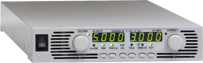
PS-UUT-L1 Programmable Power Supply
The PS-UUT-L1 programmable power supply option is used to provide UUT power for functional test and device programming with MultiWriter.
| Features | |
|
|
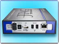
GPIB IEEE-488 Controller (GPIB-USB)
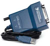
The GPIB IEEE-488 option allows you to connect and control external instrumentation with the CheckSum test system.
The GPIB-USB option can directly control GPIB instruments from within the CheckSum System software or you can write your own software using the included documentation. The GPIB-USB connects to an unused test system USB connector and to IEEE-488 instruments. This controller does not require a GPIB cable to connect to your instruments. You can attach it directly to the GPIB port on your instrument and then connect the USB cable to the USB port. If you have multiple instruments in a daisy-chain or star configuration, attach any cables that connect to the other instruments first, and then connect the GPIB as the last connector in the stack.
Model DIG-1 Digital I/O Module
The Model DIG-1 module can be used to power-up and functionally test circuit assemblies with digital I/O signals.
The Model DIG-1 is controlled by CheckSum’s Visual ICT/MDA™ for Windows software. This software provides a variety of software functions to create a flexible test environment. The DIG-1 digital I/O pins can also be controlled by boundary-scan.
The DIG-1 module provides 48 relay-isolated digital I/O pins and Visual ICT/MDA test systems can be configured with 96 pins per system. The module supports 3.3V and 5V logic levels. Relay-isolation allows the DIG-1 module to be used with integrated ICT/MDA and functional test fixtures.
The Model RM-1 general purpose Relay Module can be installed in an unused controller (PC) slot. It provides eight undedicated relays, four form-C and four form-A, rated at 1A. This relay module can be used for switching UUT power or signals, and also includes eight optically-isolated, high-voltage digital inputs. The Model RM-1 installs in a short PC expansion slot and has a 37-pin D-Sub back-panel connector.
50 Test Point Switch-Over Board (FIX-50P-SWO)
The FIX-50P-SWO is a 50-pole double-throw relay board normally mounted inside the fixture. It can be used to disconnect test points to eliminate loading, prevent overvoltage at the test inputs, switch test points between analog and digital signals, or to discharge the UUT prior to testing. A single TTL input signal controls all the relays. The relays are powered by a +12VDC source such as the PC’s power supply.
17 Test Point Switch-Over Board (FIX-17P-SWO)
The FIX-17P-SWO is a 17-pole double-throw relay board normally mounted inside the fixture. Relay contacts are accessed through common (COM), normally closed (NC), and normally open (NO) with each set on 17-pin headers and the relays are DPDT non-latching. This board is used to connect signals during functional test, share system resources between multiple UUTs, or provide isolation for ICT points. Works with +12V and DIG outputs from PWR-2 or FUNC-2B module.
16 Test Point Independent Relay Board (FIX-16P-IRB)
This board has independent control of 8 relays, each with 2 contacts and is normally mounted inside the fixture. It can be used to disconnect test points to eliminate loading, prevent overvoltage at the test inputs, switch test points between analog and digital signals, or to discharge the UUT prior to testing. Each of the 8 control signals activate 1 relay with 2 contacts. The relays are powered by a +5VDC source such as a system power supply. This board is used to connect signals during functional test, share system resources between multiple UUTs, or provide isolation for ICT points. Works with +5V and DIG outputs from PWR-2 or FUNC-2B module.
The Model FUNC-2 provides 16 relay-switched test points at its back panel. These test points can be expanded in 50-point increments by adding Model TR-6-1 Relay Modules (up to six TR-6-1 modules can be configured into a system).
The relay test points are used for UUT connections that exceed ± 12 volts with respect to the computer chassis when power is applied to the UUT. The Model FUNC-2 can make DMM and Counter/Timer measurements at these points. In addition, unguarded 2-wire ICT measurements (e.g. resistance, capacitance and inductance) can be made through these points. Each TR-6-1 module uses one full-length/full-height chassis slot.
TR-6-2 Fixture Interface Module
The Model TR-6-2 Fixture Interface Module provides various special functions in the test fixture. It includes two double-contact 10A power relays for switching UUT power. Optionally, it can be populated with six additional TR-6-2-RLY power relays, a dual-channel counter-timer buffer/prescaler (TR-6-2-CT), two DMM differential buffer/amplifiers (TR-6-2-DMM), and up to four 17-point switch-over modules each using two power relay sockets (TR-6-2-SWO). A breadboard area provides room for custom circuitry such as DC-DC converters. Other TR-6-2 accessories include cabling for direct connection to CheckSum’s vacuum receiver interface (50-pin is TR-6-2-THC, 17-pin is TR-6-2-SWC). All the FUNC-2 back-panel connections (relay-isolated fused power, digital and analog I/O, relay-switching) are available on the TR-6-2.
The Fixture Interface includes standoffs for easy mounting inside the fixture or on any flat surface. The 50-pin ribbon cable from the Model FUNC-2 back panel can be directly plugged into the Fixture Interface. Alternatively, when used inside a Model TR-3A vacuum test head, the special Model TR-6-2-THC plugs directly from the Fixture Interface to the inside of the fixture wiring block connected to the Model FUNC-2.
The basic Fixture Interface contains two power relays, connectors and interface circuits. You can install your own components to tailor it to your application or purchase kits from CheckSum to populate it as necessary:
The TR-6-2-SWO switch-over modules install into the power-relay sockets. Each TR-6-2-SWO, which uses two relay sockets, allows change-over of up to seventeen test points to select different source/measurement electronics or to locally isolate test points in the fixture to minimize capacitive loading on selected UUT points during power-on testing.
Boundary-Scan Partners
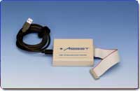
Asset InterTech
ASSET’s JTAG ScanWorks is a cohesive environment that delivers powerful test and on-board programming and configuration capabilities based on boundary-scan (IEEE 1149.1 JTAG) technology.
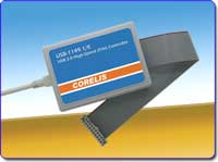
Corelis
Corelis’ ScanExpress™ Boundary-Scan (JTAG) systems offer complete solutions for prototype debug, manufacturing, and In-System Programming (ISP) of CPLDs and Flash memories. Design and test engineers can develop boundary-scan tests during the product’s development and prototype stages and then reuse the vectors in manufacturing, significantly reducing test development time and costs.
JTAG Technologies
JTAG Technologies, the world leader in IEEE 1149.1 boundary-scan applications, provides a wide range of proven solutions for JTAG testing.
![]()
Goepel Electronic
GÖPEL electronic has been among the first vendors to launch respective tools. Today we offer you the widest range of tools to benefit from the various features IEEE Std 1149.x has to offer. As a leading vendor of Intelligent Solutions for Extended JTAG/Boundary Scan, GÖPEL electronic not only provides stand-alone Boundary Scan solutions, but also is an ideal system integration partner for the combination of this technology with AOI systems, Flying Probe, Functional, and In-Circuit Testers.
CheckSum test systems can be enhanced with a variety of options and accessories that will enhance your system’s performance and convenience.
Model T-120-2U Industrial 40-Column Strip Printer
40-Column Strip Printer
The CheckSum T-120-2U Industrial Strip Printer can be used to print test results. It is compact and the 40 column print-out can be easily removed to accompany the assembly being tested. You may also want to use a standard 80-column printer with your system for printing test programs, statistical process control (SPC) reports and other files.
Model T-120-3 Foot Switch
Foot Switch
CR-2 Milli-Ohm Meter Module
The CR-2 module is used to test low-resistance components on circuit assemblies such as connectors, relay contacts, PCB traces, and shunt resistance. The CR-2 can make accurate milli-ohm resistance measurements with 2W, 200mW, and 20mWranges
CM-3 Calibration/Verification Module/Fixture
The Model CM-3 Calibration/Verification Module/Fixture provides external confirmation of the system’s calibration. The CM-3 Module/Fixture includes precise components that verify the accuracy of the Analyst series, TR-8 or TR-4 measurement systems with the included software. The CM-3 can be used for test system traceability to the National Institute of Standards and Technology (NIST). The Model CM-3 reference components can also be characterized in an external calibration lab for traceability. The CM-3 provides the traceability typically required in ISO 9000 certified sites. The unit can be purchased without traceability documentation certificate or with traceability documentation (order the Model CM-CAL).
The calibration accessory can be purchased as a separate module (Model CM-3) or integrated into a test fixture (e.g., CM-3-KIT2KN, CM-3-KIT1000 or CM-3-KIT600).
Operator’s Keypad
The Model TR-8-KEYPAD allows the operator to use the TR-8/TR-10 system without a standard keyboard. The keypad provides three system status LEDs (green for pass, red for fail, amber for busy). The keypad has eight keys for operator control. F1 through F7 keys are used for most operations such as next-test or retest, and the ESCape key aborts most operations. The keypad is connected directly to the System Module back panel.
ICT Fixture Storage System
The Model FIX-P-STORAGE is a new fixture kit storage system with built-in handles. This option replaces the four tubes and bolts used to assemble the pneumatic fixture kits for storage. This kit storage option can be used on any of the fixture kits for the TR-7 or TR-9 series pneumatic fixture systems.
AC-1 Pneumatic Controller
The Model AC-1 Pneumatic Controller is designed to allow automatic control of pneumatic air cylinders. A single TTL/CMOS signal or contact closure actuates an electric solenoid inside the AC-1 directing air from the Input port to either the Engage or Disengage output ports.
Model AC-1 Specifications:
| Line Voltage | 115/230VAC, 50/60Hz, 25VA |
| Air Switching | Dual action, 50-120PSI Quick Connect Air In, Engage and Disengage Ports |
| Manual Control | Engage, Remote or Disengage |
| Remote Control | 5V CMOS/TTL signal (pull low) or contact closure to engage air |
| Interlock Control | 5V CMOS/TTL signal (pull low) or contact closure to inhibit air |
| Air Ports | Input: 0.25 inch industrial interchange male fitting, or 0.125 inch NPT female connection Engage: 0.25 inch O.D. tubing Disengage: 0.25 inch O.D. tubing |
| Overall Size | 3.25″ W x 10.5″ D x 4.25″ H |
VC-1 Vacuum Controller
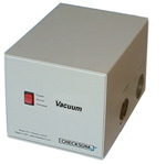
VC-1 Vacuum Controller
The Model VC-1 Vacuum Controller is designed to allow automatic control of vacuum. It is typically used to control bed-of-nails test fixturing. The VC-1 is a small, standalone unit with a switch for manual operation or it can be controlled remotely. A single TTL/CMOS signal or contact closure actuates a 3-way vacuum valve inside the VC-1 to either connect or disconnect vacuum from the test fixture.
When vacuum is disconnected, the test fixture side of the valve is vented to ambient air, allowing the fixture to quickly disengage.
VC-1 Specifications:
| Line Voltage | 115/230VAC, 50/60Hz, 25VA |
| Vacuum Switching | 3-Way: Connect vacuum and close exhaust Disconnect vacuum and open exhaust to test fixture |
| Manual Control | Engage, Remote or Disengage |
| Remote Control | 5V CMOS/TTL signal (pull low) or contact closure to engage vacuum |
| Vacuum Ports | Input has 0.75 inch NPT female connection Output has 0.75 inch NPT female connection |
| Overall Size | 6″ W x 8″ D x 5.5″ H |
DM-1 Discharge System
The CheckSum Model DM-1 Discharge System isolates and protects the MDA test system electronics from an electrically charged unit-under-test (UUT). Normally, UUTs do not become electrically charged during the manufacturing process, however, functional or system testing may leave an electrical charge on a UUT. The DM-1 will protect the test system from a UUT that may have become electrically charged with up to 250 volts. The CheckSum DM-1 also protects the test system from severe static charges on a UUT. The Model DM-1 is connected between the test fixture and the MDA test system electronics. Special internal circuitry in the DM-1 prevents the MDA electronics from being connected if a charge exists.
The CheckSum test system software can detect a charged UUT and wait for the discharge. The overvoltage charge is automatically discharged. Once the UUT voltage has been discharged to a safe level, normal testing with the MDA test system can proceed. The standard CheckSum test system multiplexer cables connect to the rear of the Model DM-1. A second test cable is provided with each 50-pin discharge module to connect to the fixture.
Installing additional discharge modules in the Discharge System is quick and easy. Each DM-1-SW plug-in card protects 50 test points in the test system. The Model DM-1 can accommodate twenty Model DM-1-SW Switch Modules. A completely configured Model DM-1 Discharge System allows isolation and protection of 1000 test points. Additional Discharge Systems can be daisy-chained for higher pin-count systems.
Model DM-1 Specifications
| Front Panel LEDs | Power-on, Discharging, Unprotected |
| Front Panel Control | Discharge, Auto (Remote), Bypass |
| Rear Panel Control | On/Off Power Switch |
| Software Control | Fixture Control (FIXCT) |
| Weight | Approximately 16 lbs. (shipping wt. approximately 20 lbs.) |
| Overall Size | 17″W x 9″D x 6.25″H |
| Capacity | 1000 Points |
| Output Cables | 36 in. |
| AC Input | 100-120VAC 50/60Hz 200-230VAC 50/60Hz |
| AC Power | 75VA maximum |


