


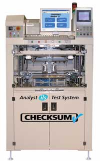
Designed for testing all types of circuit assemblies the CheckSum Analyst ils has all the features of the Analyst ems, but in a package with an integrated high-speed board handler for use in an automated production and test line. The CheckSum Analyst ils combines manufacturing process testing with TestJet Technology for high fault coverage in circuit test of a single assembly or a panel of multiple assemblies in minimum time with maximum fault coverage.
Providing features such as periodic sampling of UUTs passing down the line and automated recompression of probes and/or automatic retesting on failures, the Analyst ils meets sophisticated testing needs.
The Analyst ils performs effective power-down testing for most analog or digital assemblies being manufactured today quickly and easily testing through-hole and SMT circuit board assemblies for common manufacturing defects such as incorrect, missing or misoriented components, and opens and shorts. Equipped standard with TestJet Technology, Analyst can identify opens in and around most analog and digital IC packages. These faults comprise the vast majority of problems encountered in the today’s electronics manufacturing environment.
The optional power-up functional test capability is ideally suited for lower frequency analog assemblies with some digital content.
The Analyst ils tests the entire unit-under-test (UUT) and individual components without power applied to the UUT. Using sophisticated measurement techniques such as DC or complex-impedance measurements in conjunction with multi-point guarding, ICT systems quickly and accurately measure continuity, capacitors, resistors, inductors, voltages, semiconductor junction voltages, and SMT connections for opens. By finding the majority of faults while the UUT is in the safe unpowered mode, together with very specific fault diagnostic messages, faulty UUTs can be repaired quickly.
| There are two versions of the Analyst ils handler; standard and -43. The standard model accommodates boards up to 340mm by 254mm (13.4 inches wide and 10 inches deep). The -43 model is designed to accommodate boards up to 400mm by 300mm (15.7 inches wide and 11.8 inches deep). |
The Analyst ils is designed to SMEMA standards for straightforward integration into your production or testing line. The standard configuration is complete for most testing operations and features safety interlocks essential to automated operation.
CheckSum can ship the system to you complete with a ready-to-use test fixture and test program for one or more of your UUTs. You can use CheckSum’s fixturing division to handle all of your fixturing and programming needs; or you can modify or add UUTs yourself or with the use of third-parties.
To configure the system for testing, easily removable, cableless fixture kits are installed without the need for tools. Test fixture change-over takes only a few seconds.
The system uses the SMEMA signals to automatically signal a loader, move the assembly into the testing position, test the assembly, and unload each assembly without an operator. Once the test is completed, the system displays the results. The system can be configured to automatically produce a test report, or can be setup so that results are saved for statistical analysis (SPC) with the included software.
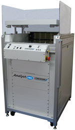
The optional offline test development station is used for test fixture development and program debug. Instead of taking valuable production time from the Analysis ils, this lower cost station is used. The offline test development station is designed to use the KIT2000-ILS-43 fixture kits, compatible with the -43 version of the Analyst ils.
The offline development station will need the same test resources (test modules, power supplies, etc) available in the Analyst ils system. Unlike the Analyst ils, the offline station requires an operator to load and unload boards. For safety, back and side panels are provided to keep objects away from the moving parts and the front panel operator buttons require two-hands to lower and raise the top lid.
For component in circuit testing, the Analyst system provides effective tools to find most faults. These measurements are made with signal injection/measurement, but without the UUT powered-on — greatly simplifying test programming and — reducing ongoing application cost. Measurements are taken at high speeds using a solid-state multiplexing system.
Opens/Shorts
Analyst can test from each point to each other point to detect faults. Open/short thresholds are typically in the 10 ohm range, but can be programmed over the range of 2 ohms to 50Kohms. Continuity tests can use 10mA, 1mA or 100µA source current. Specified pairs of points can be designated as „no-cares” to allow the most effective diagnostics or to deal with points that are near threshold values.
Resistance Measurements
Analyst provides the ability to measure from 0 ohms up to 19Mohms using various techniques to optimize the measurement effectiveness. You can choose between using a constant-current source (0.1µA to 10mA), a DC constant-voltage source (.02V to 2V full range), or AC complex-impedance measurements over the range of 100Hz – 1KHz. Resistance tests can be used with external sense (4-wire Kelvin measurements), and in conjunction with multi-point guarding to isolate individual components. Guard currents up to 100mA are available. Up to 16 distinct measurement and stimulus functions can be active during a single measurement.
Capacitance Measurements
Analyst provides the ability to measure from a few pF up to 20,000µF. You can choose between using a constant-current pulsed source (1mA to 10mA), or AC complex-impedance measurements over the range of 100Hz to 100KHz. Capacitance tests can be used with external sense (4-wire Kelvin measurements), and in conjunction with multi-point guarding to isolate individual components. Guard currents up to 100mA are available. Up to 16 distinct measurement and stimulus functions can be active during a single measurement.
Inductance Measurements
Analyst provides the ability to measure from a few µH up to 1000H. Measurements are made by using complex-impedance measurements with stimulus frequencies between 100Hz and 100KHz and full-range amplitudes of .02V to 2V. Inductance tests can be used with external sense (4-wire Kelvin measurements), and in conjunction with multi-point guarding to isolate individual components. Guard currents up to 100mA are available. Up to 16 distinct measurement and stimulus functions can be active during a single measurement.
Voltage Measurements
For UUTs that have batteries, DC amplitudes up to 10 volts can be measured. Fully differential measurements can be made up to ±8V from chassis ground.
Transistors
Transistors can be tested as two diode junctions, or tested for Beta while in circuit. The Beta test can help determine proper insertion polarity for transistors that can be installed backwards, but with the base still in the middle. This type of fault cannot typically be detected with diode testing of the junctions.
FETs
FETs can be tested for turn-on voltage. By sweeping a voltage into the gate while monitoring the Source/Drain impedance, the FET can be checked for proper orientation and operation.
Opto-Isolators
Opto-isolators can be tested by sourcing into the input leads while measuring the output impedance. By testing each device in the on and off state, high confidence is obtained.
Relays
Up to 24V with up to 100mA can be used to actuate relay coils. This allows testing of contacts in each state to ensure that the contacts are not shorted, and that the coil is operational.
Diodes
Diodes are tested by providing a constant current source (0.1µA to 100mA), then measuring the forward voltage drop, which is typically in the 0.6V to 0.8V range. This test ensures that the diode is installed, is in the proper orientation, and is not open or shorted.
Zener Diodes
Zeners are tested by providing a constant current source (0.1µA to 100mA), then measuring the forward voltage drop. Measurements up to 50V can be performed. This test ensures that the zener diode is installed, is in the proper orientation, and is not open or shorted. Zeners that cannot be brought to their full voltage due to current or voltage limiting can be tested as normal diodes or in some cases can be tested during the power-up stage.
LEDs
LEDs are tested like signal diodes, but normally have higher forward voltage drop. Special light-sensing probes can be added to customized test fixtures to detect brightness and color of LEDs and incandescent lamps.
Transformers
Transformers are typically tested for dc resistance of each coil to detect presence. Coils can also be tested for inductance, and a polarity test can be used to ensure that each coil is wired correctly. This can detect faults inherent to hand-loading of transformers with wire leads.
IC Presence/Orientation
IC’s are tested by using the ICs test. This test measures each IC pin to specified pins such as VCC, VSS or VDD, checking for the presence of the IC’s internal protection diodes. This test detects most faults such as shorted pins, open pins or mis-clocked or wrong ICs. In some cases, faults may not be detected if the IC pins are bussed or devices of similar pin-topology are interchanged.
IC Pin Connections
With the use of TestJet Technology, Analyst can detect opens to IC pins, even though the pin is bussed to other ICs. This advanced technology (licensed to CheckSum by Agilent), uses a sophisticated software/hardware algorithm to measure the minute capacitance between the PCB and the IC for each pin. If a pin is open, the capacitance significantly decreases. This technology can be used for most non-power and ground lines on the ICs and on many connectors to ensure proper connection and/or presence of the connector.
Capacitor Polarity based on TestJet Technology
In some cases, constant-current and voltage measurements of a polarized capacitor can be used to detect incorrect polarity since the capacitor draws additional current as the voltage increases in the incorrect polarity. As a practical matter, this technique cannot be used in many cases during in circuit testing because of voltage or parallel impedance limitations. In this case, the SMT option can be used to detect the polarity of most axial/SMT aluminum and tantalum capacitors up to about 200µF.
Power Module
The Analyst system includes a power module that can be used to provide higher current outputs to actuate UUT relays, power-up low power UUTs, provide additional guard current, or apply stimulus for power-up testing. The module has dual voltage-programmable high current outputs that can be set from +12V to -12V (up to 24V differential). For switching these outputs to the UUT, 16 relay test point outputs are provided. Voltage and current output can be monitored. Fixed switched supplies provide +12V, +5V and -12V at the back panel. These outputs can be switched on or off via on-board relays. The outputs are fused for protection of the system and UUT. Eight additional digital pins can be used for digital input/output or to energize external relays.
Digital I/O Option
Analyst can be configured with an optional 48 or 96 digital I/O pins. These pins can be relay-connected to the UUT in byte increments. Within each byte, each pin can be set to be an input (tri-state output) or an output. Since each pin has a 10KW pull-up (in conjunction with totem-pole outputs), it is compatible with most logic families. VCC for output can be selected to be +5V or +3.3V.
Boundary-Scan Option
The Analyst ils can be configured with the optional Boundary-Scan Test. This allows the System to be used with UUTs that have been designed to accommodate boundary-scan, or have on-board devices that support boundary-scan. In addition, boundary scan can be used by some programmable devices to perform in-system programming and program verification.
MultiWriter ISP Device Programming
The Analyst ils can be equipped with the MultiWriter ISP programming and verification capability to simultaneously program up to 384 ISP devices in circuit.
Other System I/O
In addition to the power/stimulus/measurement capabilities already mentioned, the System has a number of other functions available. These include 8 bits of Digital I/O / Relay drivers (PWR-2) and 2 Switched grounds (PWR-2)
System Switching Topology
Analyst offers a flexible switching topology to minimize custom circuitry and to allow assemblies to be easily programmed.
The system uses an N x 16 solid-state analog bus that allows each test point to be a measure source high, measure source low, measure sense high, measure sense low, guard source, guard sense, or DC/AC signal source. The solid-state matrix provides high-speed and reliability for power-down testing, or for functional testing of points that do not exceed ±12V referenced to the computer chassis.
A 16 x 2 relay matrix is also included for signals in excess of 10mA, or for voltages greater than ±12Vdc (i.e., Zener measurements).
Digital test points are available at the fixture interface blocks. They can be relay-disconnected during power-down test, then enabled (by byte) during power-up test.
Power outputs are available at the fixture interface blocks. They can be relay disconnected during power-down test. This includes the ground signals so that the UUT is fully floating.
Test Fixturing
The Analyst ils includes a pneumatic fixture press built into a rack-cabinet. This unit can be installed on your factory floor, and is ready for use once connected to standard compressed air and an AC outlet. The standard configuration is complete for most testing operations and the SMEMA signals integrate the unit into the automated line.
CheckSum can ship the system to you complete with a ready-to-use test fixture and test program for one or more of your UUTs. You can use CheckSum’s fixturing division to handle all of your fixturing and programming needs; or you can modify or add UUTs yourself or with the use of third-parties.
The optional CheckSum fixture kit, KIT2000-ILS-43 or KIT2000-ILS-QC, is low-cost to minimize your recurring costs. Installing the fixture kit simply involves locking the top and bottom units into place. The bottom assembly includes a fiberglass probe plate with a fixture interface section. The top assembly is a clear polycarbonate plate that is used with pressure rods to press the UUT down onto the spring-probes. It can be machined and milled with openings to allow for tall components.
To run a test, the system signals the upstream loader that the system is ready. Once the UUT enters the loading area, a conveyer automatically moves the UUT into position to be tested. The system lowers the UUT onto the spring-probes, the top moves down to compress the spring-probes and the test begins. Once the test completes, the system prepares the UUT to exit, waits until the unloader is ready, signals a Pass or Fail to the next system in-line and moves the UUT onto the unloader. Once the test is completed, the system displays the results.
The typical Analyst ils test system consists of a complete, ready to use, 800 test point system with:
The Analyst ils system can be configured with additional modules and other options that can expand the system:
If you need a different configuration, feel free to call us and discuss your application.


