


Features
Application
Programming CPLDs (Complex Programmable Logic Devices) such as serial flash memories and microcontrollers after these parts have been mounted on the printed circuit board. Since the contents of Phase Change Memory (also known as PCM, PCME, PRAM, PCRAM, and C-RAM) can be lost because of the high temperatures needed to solder the device to a board, on-board programming is required.
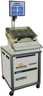
The MultiWriter pps™ on-board gang programming system uses proven, patented simultaneous programming technology to program up to 384 chips simultaneously, up to 16 different types or families — typically in seconds instead of the minutes required by conventional programmers.
Compared to other part programming solutions, MultiWriter pps delivers significant speed and cost advantages over conventional in-circuit tester-based programmers when more than four parts already mounted on circuit boards must be programmed in a single pass, making it especially effective for multi-board panels.
MultiWriter pps is optimized for applications requiring programming of at least 4 parts per board or multi-board panel. MultiWriter can simultaneously program parts on multi-board panels with 10, 20 or more boards per panel.
Advantages of On-board Part Programming with the MultiWriter pps
Product Details
The MultiWriter pps On-board Gang Programming System includes:
Purchase or Pay-Per-Use
Is Pay-Per-Use the right solution for your programmed parts?
† MultiWriter Technology is protected under U.S. Patent No. 7,802,021.
MultiWriter technology is available on CheckSum Analyst low cost in-circuit testers or in the standalone MultiWriter pps™ On-board Gang Programming System.
MultiWriter Part Programming Families
MultiWriter has a comprehensive library of supported parts families, which is being updated and expanded on an ongoing basis. The figure below shows the part manufacturers with currently supported devices in the Library. You can download an up-to-date list of supported parts by manufacturer.
Please contact CheckSum to inquire if the parts family you need is planned or currently in development.
Part Programming
The throughput of simultaneous programming with the flexibility of custom programming. MultiWriter allows unique data such as a date code or serial number for the parts to be programmed with minimal impact on programming time. The part serial number or other data such as an assembly serial number entered via bar code can be stored in a file or provided at run-time. Calibration or other measurement data can be programmed into each part separately as illustrated in the diagram below.
Smart ISP™
MultiWriter’s Smart ISP (In-System Programming) technology ensures that the ISP programming phase follows a defect-free in-circuit test of the board. The test system programs only boards that have passed the in-circuit tests. Only assemblies that have passed the opens/shorts and other component tests are powered-on. For example, if a panel has seven tested-good assemblies out of eight total, then only those seven will be powered-on for ISP device programming.
Using the Data Encryption Protection option insures your IP (Intellectual Property) is not at risk anywhere in the world. Unique data (e.g. serial number, date code, MAC address, calibration data, etc) can be written to individual chips, as they are being gang-programmed.
Board Design Considerations
As is the case in most designs, the circuit design must allow in-system programming such that the device can be programmed without the requirement to overdrive other signals. The ISP device programming pins must be accessible via a bed-of-nails fixture—just like any other in-circuit test point.
The board or multi-board panel assembly layout should provide electrical access to the programming pins that are as physically close as possible to the device being programmed in order to minimize crosstalk and noise.
Device Programming Considerations
MultiWriter allows unique data such as a date code or serial number for the parts to be programmed with minimal impact on programming time. The part serial number or other data such as an assembly serial number entered via bar code can be stored in a file or provided at run-time. Calibration or other measurement data can be programmed into each part separately. Since unique data is typically a very small portion of the overall part memory, the programming time for chip-unique data will be minimal. A standard data file format (INTEL hex, Motorola S-Record, SVF, STAPL) is used for storage of unique data that is accessed during the ISP programming process.
The MultiWriter Controller board has two operating modes: Program and Verify. In Program mode, the controller places the ISP chip in the “program” state and code appropriate to the device is retrieved from the computer memory and applied via the fixture-based buffer boards. Once chip programming is complete, the MultiWriter controller places the chip in the “read” state and the code just programmed is verified. The Program and Verify operations can occur on a Test Step basis.
The board assembly (or individual panel in a multi-up assembly) will be powered-up to program the part, so some test system power source must be available and sufficient.
* Up to 16 MultiWriter control modules with up to 24 buffer modules each for 384 maximum devices. One MultiWriter control module required for each different device type.
† MultiWriter Technology is protected under U.S. Patent No. 7,802,021.
MultiWriter On-Board Gang Part Programming
Programming CPLD (Complex Programmable Logic Device) parts such as microcontrollers, serial Flash and FPGAs after they are attached to the circuit board [’on-board programming’] simplifies the manufacturing process and reduces inventory and rework costs compared to mounting pre-programmed chips.
Since the contents of Phase Change Memory (also known as PCM, PCME, PRAM, PCRAM, and C-RAM) can be lost because of the high temperatures needed to solder the device to a board, on-board programming is required.
Simultaneous Part Programming
MultiWriter uses patented simultaneous programming technology to simultaneously program up 384 chips at one time, up to 16 different types — usually in seconds instead of the minutes required by conventional programmers.
MultiWriter technology has already programmed millions of parts on millions of boards. Its ability to program up to 384 chips at once makes MultiWriter the industry’s most productive on-board part programmer.
MultiWriter Multiplies Productivity Two Ways
MultiWriter technology is available on CheckSum Analyst low cost in circuit testers or in the new standalone MultiWriter pps™ on-board gang programming system where at least four parts need to be programmed on a board or multi-board panel.
MultiWriter installed in an Analyst series in circuit tester:
MultiWriter pps used following the traditional in circuit tester:
MultiWriter Features & Benefits
MultiWriter technology is a clean, low cost solution to increase part programming productivity–regardless of whether it’s in an Analyst in circuit tester or in the MultiWriter pps gang programming system.
MultiWriter is the first ISP programming system integrated right into the bed-of-nails fixture
Simultaneous device programming
Comprehensive device and bus algorithm library
Unique data may be programmed on a per-device basis — even on panelized boards
Fixture-mounted buffer boards ensure the highest signal quality
¹ Up to 16 MultiWriter control modules with up to 24 buffer modules each for 384 maximum devices. One MultiWriter control module required for each different device type.
† MultiWriter Technology is protected under U.S. Patent No. 7,802,021.
As CPLD memory sizes increase, fast programming times are critically important. MultiWriter delivers impressive throughput improvements over convention ICT-based part programming approaches via three key innovations:
The example multi-board panel assembly illustrated at right demonstrates how MultiWriter with simultaneous part programming multiplies throughput compared to conventional one part at a time programming.
A panel consisting of four identical boards, each with three different programmable parts (labeled A, B, C) requires 12 separate programming and verification operations using a conventional in-line part programmer.
Simultaneous programming requires only a single program/verification step that covers all twelve parts.
Each red box represents an individual programming/verification operation.
MultiWriter Simultaneous Programming:
Requires just one programming/verification step since all chips are programmed and verified in a single programming sequence.

The MultiWriter Part Programming System solves the throughput and cost problems of earlier ISP programming techniques used in-line on in-circuit testers (ICT) and with 'dongle’-based approaches used at functional test.
Using CheckSum’s patented simultaneous programming technology to program up to 384 serial parts in a single pass, MultiWriter technology makes on-board part programming practical, affordable and productive.
And fast. Serial Flash, EEPROMS, embedded microcontrollers, and FPGAs are programmed at near-data book speeds. Since the contents of Phase Change Memory (also known as PCM, PCME, PRAM, PCRAM, and C-RAM) can be lost because of the high temperatures needed to solder the device to a board, on-board programming is required.
Using the Data Encryption Protection option insures your IP (Intellectual Property) is not at risk anywhere in the world. Unique data (e.g. serial number, date code, MAC address, calibration data, etc) can be written to individual chips, as they are being gang-programmed.
A unique test fixture-based controller and buffer card architecture reduces cost, improves signal quality. A USB 2.0 bus directly from the controller to computer and MultiWriter software designed for speed complete the productivity equation.
Software architecture enables simultaneous part programming
MultiWriter’s ability to program ISP devices simultaneously rests on its patented architecture that allows it to program up to 384 serial ISP devices per board or multi-up panel at high speed.
The total programming time is identical for a single chip on a single board, one chip per board on a multiple panel assembly, or any combination in between. Device-specific code is programmed following the simultaneous programming step. Since the amount of device-specific code is small compared to the code common to all chips, total programming time is affected very little, if at all.

For example, benchmark results conducted by CheckSum show that MultiWriter can program one or five Freescale 9S12H128 microcontrollers in the same amount of time using the BDM (Background Debug Mode) bus. Programming speed is limited by the chip, while the memory size for this microcontroller is 128k, but only 64k was programmed. With MultiWriter, the software overhead, programming, and verification took a total of 12.21 seconds (0.61 seconds software overhead, 6.13 seconds programming, and 5.47 seconds verification) for one device or for five devices, or more.
MultiWriter hardware is designed for low cost and high signal speedsMultiWriter hardware consists of two elements:
The controller and as many buffer boards as required are mounted inside test bed-of-nails test fixture. This cost-effective design eliminates the requirement to modify the test system or install costly special-purpose channel cards.
Any MultiWriter-equipped fixture can be used on any CheckSum Analyst test system equipped with MultiWriter software on its PC or on the MultiWriter pps On-board Gang Programming System.
Short wire lengths between the buffer boards and the device being programmed/verified is ideal for dealing with increasing programming speeds.
MultiWriter ISP System Computer Interface
Controller Board
Buffer Board
Note: The MultiWriter ISP System is appropriate for circuit boards and multi-board panel assemblies requiring on-board code programming and verification of serial bus ISP devices. MultiWriter is available only as an integrated element of a CheckSum-developed application package that includes a bed-of-nails fixture and associated test program operating on an Analyst in-circuit test system or on the MultiWriter pps On-board Gang Programming System.
* Up to 16 MultiWriter control modules with up to 24 buffer modules each for 384 maximum devices. One MultiWriter control module required for each different device type.
† MultiWriter Technology is protected under U.S. Patent No. 7,802,021.
The MultiWriter Part Programming System solves the throughput and cost problems of earlier ISP programming techniques used in-line on in-circuit testers (ICT) and with 'dongle’-based approaches used at functional test.
Using CheckSum’s patented simultaneous programming technology to program up to 384 serial parts in a single pass, MultiWriter technology makes on-board part programming practical, affordable and productive.
And fast. Serial Flash, EEPROMS, embedded microcontrollers, and FPGAs are programmed at near-data book speeds. Since the contents of Phase Change Memory (also known as PCM, PCME, PRAM, PCRAM, and C-RAM) can be lost because of the high temperatures needed to solder the device to a board, on-board programming is required.
Using the Data Encryption Protection option insures your IP (Intellectual Property) is not at risk anywhere in the world. Unique data (e.g. serial number, date code, MAC address, calibration data, etc) can be written to individual chips, as they are being gang-programmed.
A unique test fixture-based controller and buffer card architecture reduces cost, improves signal quality. A USB 2.0 bus directly from the controller to computer and MultiWriter software designed for speed complete the productivity equation.
Software architecture enables simultaneous part programming
MultiWriter’s ability to program ISP devices simultaneously rests on its patented architecture that allows it to program up to 384 serial ISP devices per board or multi-up panel at high speed.
The total programming time is identical for a single chip on a single board, one chip per board on a multiple panel assembly, or any combination in between. Device-specific code is programmed following the simultaneous programming step. Since the amount of device-specific code is small compared to the code common to all chips, total programming time is affected very little, if at all.
For example, benchmark results conducted by CheckSum show that MultiWriter can program one or five Freescale 9S12H128 microcontrollers in the same amount of time using the BDM (Background Debug Mode) bus. Programming speed is limited by the chip, while the memory size for this microcontroller is 128k, but only 64k was programmed. With MultiWriter, the software overhead, programming, and verification took a total of 12.21 seconds (0.61 seconds software overhead, 6.13 seconds programming, and 5.47 seconds verification) for one device or for five devices, or more.
MultiWriter hardware is designed for low cost and high signal speedsMultiWriter hardware consists of two elements:
The controller and as many buffer boards as required are mounted inside test bed-of-nails test fixture. This cost-effective design eliminates the requirement to modify the test system or install costly special-purpose channel cards.
Any MultiWriter-equipped fixture can be used on any CheckSum Analyst test system equipped with MultiWriter software on its PC or on the MultiWriter pps On-board Gang Programming System.
Short wire lengths between the buffer boards and the device being programmed/verified is ideal for dealing with increasing programming speeds.
MultiWriter ISP System Computer Interface
Controller Board
Buffer Board
Note: The MultiWriter ISP System is appropriate for circuit boards and multi-board panel assemblies requiring on-board code programming and verification of serial bus ISP devices. MultiWriter is available only as an integrated element of a CheckSum-developed application package that includes a bed-of-nails fixture and associated test program operating on an Analyst in-circuit test system or on the MultiWriter pps On-board Gang Programming System.
* Up to 16 MultiWriter control modules with up to 24 buffer modules each for 384 maximum devices. One MultiWriter control module required for each different device type.
† MultiWriter Technology is protected under U.S. Patent No. 7,802,021.


