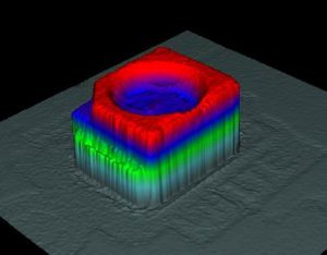
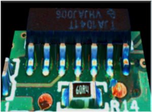
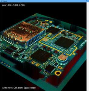
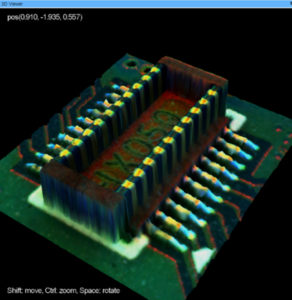
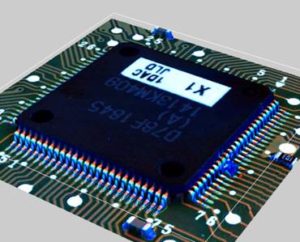
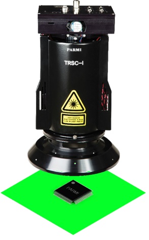
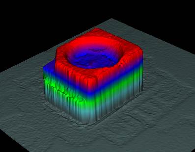
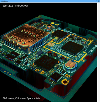
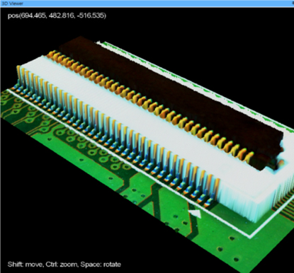
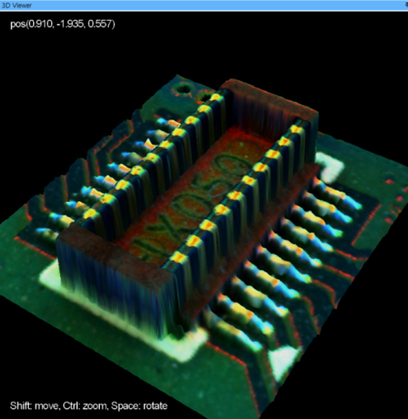
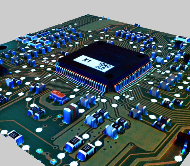
Pierwsze prawdziwe AOI – 3D !
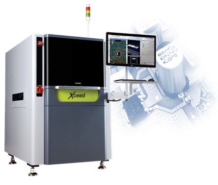
Inspekcja 3D + 2D w jednym cyklu
Najszybszy Czas cyklu
Hardware & Software
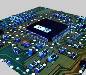
Zero False Call Rate
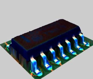
Beyond 2D AOI
High Credibility of Real Defect Detection
Zobacz także


Znakowanie promieniem lasera płytek, to najtrwalsza metoda ich oznaczania. Poniżej przestawiamy rozwiązania w tym zakresie, produkowane przez koreańską firmę YJ-LINK.
Every test system installation has different requirements. That’s why CheckSum provides a long list of options and accessories that tailor the installation to fit your needs.
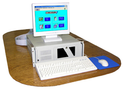
CheckSum test controllers are used to control the test system software and electronics. The CheckSum test system resources (modules/boards) are installed in a separate industrial chassis. You can use your existing PC or purchase one from CheckSum. If a test system is purchased with a PC controller, the test system is shipped configured, tested, and covered under a single warranty.
Since the PC industry rapidly changes, contact CheckSum about present or alternative configurations.
System PC with 20 Slot Chassis for Test System Resources
System PC Dimensions:
12.45 in. (H) x 13.40 in. (D) x 3.65 in. (W)
316mm x 340mm x 92.7mm
System PC Slots:
1 low-profile PCI
(H: 2.5 in. x L: 6.6 in.)
1 low-profile PCIe x16 graphics
(H: 2.5 in. x L: 6.6 in.)
20-Slot Chassis Dimensions:
17 in. (W) x 22 in. (D) x 7 in. (H)
432mm x 559mm x 178mm
In order to accommodate the complexities of power-on functional testing, CheckSum offers a selection of accessories. Some of these mount into controller (PC) expansion slots, while others are typically mounted in available rack space or inside the test fixture (in close proximity to the UUT connections). The fixture-mounted accessories are installed with screws through provided standoffs. Connections are made with standard ribbon-cable connectors or wire-wrapping.
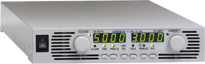
PS-UUT-L1 Programmable Power Supply
The PS-UUT-L1 programmable power supply option is used to provide UUT power for functional test and device programming with MultiWriter.
| Features | |
|
|
GPIB IEEE-488 Controller (GPIB-USB)
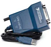
The GPIB IEEE-488 option allows you to connect and control external instrumentation with the CheckSum test system.
The GPIB-USB option can directly control GPIB instruments from within the CheckSum System software or you can write your own software using the included documentation. The GPIB-USB connects to an unused test system USB connector and to IEEE-488 instruments. This controller does not require a GPIB cable to connect to your instruments. You can attach it directly to the GPIB port on your instrument and then connect the USB cable to the USB port. If you have multiple instruments in a daisy-chain or star configuration, attach any cables that connect to the other instruments first, and then connect the GPIB as the last connector in the stack.
Model DIG-1 Digital I/O Module
The Model DIG-1 module can be used to power-up and functionally test circuit assemblies with digital I/O signals.
The Model DIG-1 is controlled by CheckSum’s Visual ICT/MDA™ for Windows software. This software provides a variety of software functions to create a flexible test environment. The DIG-1 digital I/O pins can also be controlled by boundary-scan.
The DIG-1 module provides 48 relay-isolated digital I/O pins and Visual ICT/MDA test systems can be configured with 96 pins per system. The module supports 3.3V and 5V logic levels. Relay-isolation allows the DIG-1 module to be used with integrated ICT/MDA and functional test fixtures.
The Model RM-1 general purpose Relay Module can be installed in an unused controller (PC) slot. It provides eight undedicated relays, four form-C and four form-A, rated at 1A. This relay module can be used for switching UUT power or signals, and also includes eight optically-isolated, high-voltage digital inputs. The Model RM-1 installs in a short PC expansion slot and has a 37-pin D-Sub back-panel connector.
50 Test Point Switch-Over Board (FIX-50P-SWO)
The FIX-50P-SWO is a 50-pole double-throw relay board normally mounted inside the fixture. It can be used to disconnect test points to eliminate loading, prevent overvoltage at the test inputs, switch test points between analog and digital signals, or to discharge the UUT prior to testing. A single TTL input signal controls all the relays. The relays are powered by a +12VDC source such as the PC’s power supply.
17 Test Point Switch-Over Board (FIX-17P-SWO)
The FIX-17P-SWO is a 17-pole double-throw relay board normally mounted inside the fixture. Relay contacts are accessed through common (COM), normally closed (NC), and normally open (NO) with each set on 17-pin headers and the relays are DPDT non-latching. This board is used to connect signals during functional test, share system resources between multiple UUTs, or provide isolation for ICT points. Works with +12V and DIG outputs from PWR-2 or FUNC-2B module.
16 Test Point Independent Relay Board (FIX-16P-IRB)
This board has independent control of 8 relays, each with 2 contacts and is normally mounted inside the fixture. It can be used to disconnect test points to eliminate loading, prevent overvoltage at the test inputs, switch test points between analog and digital signals, or to discharge the UUT prior to testing. Each of the 8 control signals activate 1 relay with 2 contacts. The relays are powered by a +5VDC source such as a system power supply. This board is used to connect signals during functional test, share system resources between multiple UUTs, or provide isolation for ICT points. Works with +5V and DIG outputs from PWR-2 or FUNC-2B module.
The Model FUNC-2 provides 16 relay-switched test points at its back panel. These test points can be expanded in 50-point increments by adding Model TR-6-1 Relay Modules (up to six TR-6-1 modules can be configured into a system).
The relay test points are used for UUT connections that exceed ± 12 volts with respect to the computer chassis when power is applied to the UUT. The Model FUNC-2 can make DMM and Counter/Timer measurements at these points. In addition, unguarded 2-wire ICT measurements (e.g. resistance, capacitance and inductance) can be made through these points. Each TR-6-1 module uses one full-length/full-height chassis slot.
TR-6-2 Fixture Interface Module
The Model TR-6-2 Fixture Interface Module provides various special functions in the test fixture. It includes two double-contact 10A power relays for switching UUT power. Optionally, it can be populated with six additional TR-6-2-RLY power relays, a dual-channel counter-timer buffer/prescaler (TR-6-2-CT), two DMM differential buffer/amplifiers (TR-6-2-DMM), and up to four 17-point switch-over modules each using two power relay sockets (TR-6-2-SWO). A breadboard area provides room for custom circuitry such as DC-DC converters. Other TR-6-2 accessories include cabling for direct connection to CheckSum’s vacuum receiver interface (50-pin is TR-6-2-THC, 17-pin is TR-6-2-SWC). All the FUNC-2 back-panel connections (relay-isolated fused power, digital and analog I/O, relay-switching) are available on the TR-6-2.
The Fixture Interface includes standoffs for easy mounting inside the fixture or on any flat surface. The 50-pin ribbon cable from the Model FUNC-2 back panel can be directly plugged into the Fixture Interface. Alternatively, when used inside a Model TR-3A vacuum test head, the special Model TR-6-2-THC plugs directly from the Fixture Interface to the inside of the fixture wiring block connected to the Model FUNC-2.
The basic Fixture Interface contains two power relays, connectors and interface circuits. You can install your own components to tailor it to your application or purchase kits from CheckSum to populate it as necessary:
The TR-6-2-SWO switch-over modules install into the power-relay sockets. Each TR-6-2-SWO, which uses two relay sockets, allows change-over of up to seventeen test points to select different source/measurement electronics or to locally isolate test points in the fixture to minimize capacitive loading on selected UUT points during power-on testing.
Boundary-Scan Partners
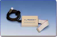
Asset InterTech
ASSET’s JTAG ScanWorks is a cohesive environment that delivers powerful test and on-board programming and configuration capabilities based on boundary-scan (IEEE 1149.1 JTAG) technology.
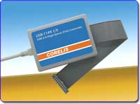
Corelis
Corelis’ ScanExpress™ Boundary-Scan (JTAG) systems offer complete solutions for prototype debug, manufacturing, and In-System Programming (ISP) of CPLDs and Flash memories. Design and test engineers can develop boundary-scan tests during the product’s development and prototype stages and then reuse the vectors in manufacturing, significantly reducing test development time and costs.
JTAG Technologies
JTAG Technologies, the world leader in IEEE 1149.1 boundary-scan applications, provides a wide range of proven solutions for JTAG testing.
![]()
Goepel Electronic
GÖPEL electronic has been among the first vendors to launch respective tools. Today we offer you the widest range of tools to benefit from the various features IEEE Std 1149.x has to offer. As a leading vendor of Intelligent Solutions for Extended JTAG/Boundary Scan, GÖPEL electronic not only provides stand-alone Boundary Scan solutions, but also is an ideal system integration partner for the combination of this technology with AOI systems, Flying Probe, Functional, and In-Circuit Testers.
CheckSum test systems can be enhanced with a variety of options and accessories that will enhance your system’s performance and convenience.
Model T-120-2U Industrial 40-Column Strip Printer
40-Column Strip Printer
The CheckSum T-120-2U Industrial Strip Printer can be used to print test results. It is compact and the 40 column print-out can be easily removed to accompany the assembly being tested. You may also want to use a standard 80-column printer with your system for printing test programs, statistical process control (SPC) reports and other files.
Model T-120-3 Foot Switch
Foot Switch
CR-2 Milli-Ohm Meter Module
The CR-2 module is used to test low-resistance components on circuit assemblies such as connectors, relay contacts, PCB traces, and shunt resistance. The CR-2 can make accurate milli-ohm resistance measurements with 2W, 200mW, and 20mWranges
CM-3 Calibration/Verification Module/Fixture
The Model CM-3 Calibration/Verification Module/Fixture provides external confirmation of the system’s calibration. The CM-3 Module/Fixture includes precise components that verify the accuracy of the Analyst series, TR-8 or TR-4 measurement systems with the included software. The CM-3 can be used for test system traceability to the National Institute of Standards and Technology (NIST). The Model CM-3 reference components can also be characterized in an external calibration lab for traceability. The CM-3 provides the traceability typically required in ISO 9000 certified sites. The unit can be purchased without traceability documentation certificate or with traceability documentation (order the Model CM-CAL).
The calibration accessory can be purchased as a separate module (Model CM-3) or integrated into a test fixture (e.g., CM-3-KIT2KN, CM-3-KIT1000 or CM-3-KIT600).
Operator’s Keypad
The Model TR-8-KEYPAD allows the operator to use the TR-8/TR-10 system without a standard keyboard. The keypad provides three system status LEDs (green for pass, red for fail, amber for busy). The keypad has eight keys for operator control. F1 through F7 keys are used for most operations such as next-test or retest, and the ESCape key aborts most operations. The keypad is connected directly to the System Module back panel.
ICT Fixture Storage System
The Model FIX-P-STORAGE is a new fixture kit storage system with built-in handles. This option replaces the four tubes and bolts used to assemble the pneumatic fixture kits for storage. This kit storage option can be used on any of the fixture kits for the TR-7 or TR-9 series pneumatic fixture systems.
AC-1 Pneumatic Controller
The Model AC-1 Pneumatic Controller is designed to allow automatic control of pneumatic air cylinders. A single TTL/CMOS signal or contact closure actuates an electric solenoid inside the AC-1 directing air from the Input port to either the Engage or Disengage output ports.
Model AC-1 Specifications:
| Line Voltage | 115/230VAC, 50/60Hz, 25VA |
| Air Switching | Dual action, 50-120PSI Quick Connect Air In, Engage and Disengage Ports |
| Manual Control | Engage, Remote or Disengage |
| Remote Control | 5V CMOS/TTL signal (pull low) or contact closure to engage air |
| Interlock Control | 5V CMOS/TTL signal (pull low) or contact closure to inhibit air |
| Air Ports | Input: 0.25 inch industrial interchange male fitting, or 0.125 inch NPT female connection Engage: 0.25 inch O.D. tubing Disengage: 0.25 inch O.D. tubing |
| Overall Size | 3.25″ W x 10.5″ D x 4.25″ H |
VC-1 Vacuum Controller
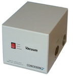
VC-1 Vacuum Controller
The Model VC-1 Vacuum Controller is designed to allow automatic control of vacuum. It is typically used to control bed-of-nails test fixturing. The VC-1 is a small, standalone unit with a switch for manual operation or it can be controlled remotely. A single TTL/CMOS signal or contact closure actuates a 3-way vacuum valve inside the VC-1 to either connect or disconnect vacuum from the test fixture.
When vacuum is disconnected, the test fixture side of the valve is vented to ambient air, allowing the fixture to quickly disengage.
VC-1 Specifications:
| Line Voltage | 115/230VAC, 50/60Hz, 25VA |
| Vacuum Switching | 3-Way: Connect vacuum and close exhaust Disconnect vacuum and open exhaust to test fixture |
| Manual Control | Engage, Remote or Disengage |
| Remote Control | 5V CMOS/TTL signal (pull low) or contact closure to engage vacuum |
| Vacuum Ports | Input has 0.75 inch NPT female connection Output has 0.75 inch NPT female connection |
| Overall Size | 6″ W x 8″ D x 5.5″ H |
DM-1 Discharge System
The CheckSum Model DM-1 Discharge System isolates and protects the MDA test system electronics from an electrically charged unit-under-test (UUT). Normally, UUTs do not become electrically charged during the manufacturing process, however, functional or system testing may leave an electrical charge on a UUT. The DM-1 will protect the test system from a UUT that may have become electrically charged with up to 250 volts. The CheckSum DM-1 also protects the test system from severe static charges on a UUT. The Model DM-1 is connected between the test fixture and the MDA test system electronics. Special internal circuitry in the DM-1 prevents the MDA electronics from being connected if a charge exists.
The CheckSum test system software can detect a charged UUT and wait for the discharge. The overvoltage charge is automatically discharged. Once the UUT voltage has been discharged to a safe level, normal testing with the MDA test system can proceed. The standard CheckSum test system multiplexer cables connect to the rear of the Model DM-1. A second test cable is provided with each 50-pin discharge module to connect to the fixture.
Installing additional discharge modules in the Discharge System is quick and easy. Each DM-1-SW plug-in card protects 50 test points in the test system. The Model DM-1 can accommodate twenty Model DM-1-SW Switch Modules. A completely configured Model DM-1 Discharge System allows isolation and protection of 1000 test points. Additional Discharge Systems can be daisy-chained for higher pin-count systems.
Model DM-1 Specifications
| Front Panel LEDs | Power-on, Discharging, Unprotected |
| Front Panel Control | Discharge, Auto (Remote), Bypass |
| Rear Panel Control | On/Off Power Switch |
| Software Control | Fixture Control (FIXCT) |
| Weight | Approximately 16 lbs. (shipping wt. approximately 20 lbs.) |
| Overall Size | 17″W x 9″D x 6.25″H |
| Capacity | 1000 Points |
| Output Cables | 36 in. |
| AC Input | 100-120VAC 50/60Hz 200-230VAC 50/60Hz |
| AC Power | 75VA maximum |
Features
Applications
Recommended TR-4 or TR-8 Replacement Test System is the Analyst ems
Recommended TR-4/6, TR-6, or TR-8/6 Replacement Test System is the Analyst ems+ft
TR-4 / TR-8 ICT/MDA Board Test Overview
CheckSum In-Circuit Test (ICT) / Manufacturing Defects Analyzers (MDAs) provide the capability to quickly and easily test assemblies for common manufacturing defects such as incorrect, missing or misoriented components, and opens and shorts. These faults comprise the vast majority of problems encountered in the typical manufacturing flow. Since MDAs have low initial purchase price and ease in programming, they provide the most cost-effective means of improving productivity. MDA systems can quickly and accurately measure continuity, capacitors, resistors, inductors, voltages, semiconductor junction voltages, and SMT connections for opens. With these basic tools, MDAs can find most faults in analog or digital assemblies before power-up. CheckSum provides a line of MDA test systems to fill the needs of different applications:
The CheckSum Analyst mc system is a low-cost, 400 test point bench top MDA test system integrated with a mechanical-advantage fixture receiver. The fixture receiver system uses quick change fixture kits.
The Model TR-4 MDA test system increases test coverage by adding the capacity for higher point counts, wider component measurement ranges, and capabilities such as complex-impedance measurement techniques and guarding.
The Model TR-8 MDA test system increases test coverage even further with a wider measurement and guarding bandwidth, higher point count, SMT-open test coverage, Boundary-Scan option, and other features.
CheckSum Cable/Harness Test Systems
These are special order systems only. Please contact CheckSum for additional information.R-90 Continuity Test System
G-50 Continuity Test System
CheckSum Model TR-9-1000-QC
Recommended TR-9-1000-QC Replacement Fixture System is the 12KN
TR-9-1000-QC Long Travel Pneumatic Fixture System Overview
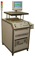
The CheckSum Model TR-9-1000-QC Long Travel Pneumatic Fixture System is designed to be the basis for CheckSum stand-alone bed-of-nails test systems. Integrated into the system is rack space for system electronics, a keyboard, and a front panel with a minimum selection of buttons to make it easy, safe, and error-free for the operator to use.
The Model TR-9-1000-QC can be used for test fixturing of circuit boards up to 13.2″ x 16″. This fixture system can be used for most general-purpose bed-of-nails fixturing applications including those with top and bottom access, and TestJet Technology*.
The Model TR-9-1000-QC utilizes a 6″ long-travel mechanism so that a lid does not need to be opened and closed between tests. The unit-under-test (UUT) is simply removed and the next one put into place. To start the test, the operator uses both hands to press and hold the Test button in conjunction with a safety button. Once the test starts, the operator can release the buttons. For extra safety, a force-sensing mechanism causes the system to release if it encounters resistance during its downward travel until the last 0.5″ of travel is reached.
CheckSum is the only automatic test equipment (ATE) supplier that offers complete turnkey packages that are ready for production when the land on your receiving dock. This means you receive optimum performance and reliability at the lowest overall cost.
Not only is the price of Analyst systems a fraction of traditional ICT, more importantly, ongoing operating costs (fixtures, programs, and support) are typically 50% less.
Our focus on minimizing fixture cost and simplifying programming saves money each time a new test job comes on line. Electronic manufacturers who switchover to CheckSum systems find the cost savings to be immediate and dramatic.
In Circuit Test Fixtures and Fixture Kits
CheckSum pneumatic and mechanical test fixtures are rugged, reliable and inexpensive-especially when compared to the heavy vacuum fixtures required by traditional in circuit testers.
CheckSum fixturing is compatible with all of CheckSum’s test systems. Since the electronics are isolated from the fixture you can use CheckSum’s factory-built fixtures or build your own special fixturing or adapters that can accommodate ribbon-cable connectors.
CheckSum can provide fixture kits for your customization or do the complete fixturing and test programming job for you.
Model 12KN Dual Level Long-Travel Pneumatic Fixture System
The 12KN Dual Level Pneumatic Fixture System is integrated into a rack-cabinet and designed to be the basis for CheckSum bed-of-nails test systems. The long-travel press eliminates the need to open and close a lid between tests. The fixture kits are easily changed by sliding the fixture top plate and base into place. The system uses a universal spring-probe fixture interface. The fixture system can accommodate up to 5200 test points and uses standard CheckSum fixture kits. Integrated into the system is rack space for system electronics and an operator keypad with a minimum selection of buttons to make it easy, safe, and error-free for the operator to use. The 12KN is compatible with existing CheckSum KIT1000-QC and KIT2KN-QC fixtures. A safety light curtain provides operator safety.
Fixture Guidelines: Assembly size can be up to (approximately) 24 x 13.2 inches (61 x 33.5 cm), dual level, single-sided and double-sided probing plus TestJet.
Model TR-7-1000-QC Pneumatic Fixture System
The TR-7-1000-QC is a new version of our popular TR-7-1000 pneumatic fixture receiver. Uses air pressure to press the assembly being tested onto spring probes. Usable to 1000 test system connections, the Model TR-7-1000-QC is ideal for most testing applications including dual-level fixturing. Using low-cost removable fixture kits, it can accommodate assemblies where adding a vacuum seal is difficult.
Fixture Guidelines: Assembly size can be up to (approximately) 16 x 13.2 inches (40.6 x 33.5 cm), dual or single-sided probing and TestJet.
Model TR-5-400-QC Mechanical-Advantage Fixture System
Designed for test fixturing of assemblies with up to 400 test points. The Fixture System consists of a reusable Fixture Press that is used in conjunction with low-cost, easily interchanged Fixture Kits.
Fixture Guidelines: Assembly size can be up to (approximately) 11.75 x 8.5 inches (30 x 21.5 cm), dual or single-sided probing and TestJet.
Model TR-5 Mechanical Bed-of-Nails Fixture Kits
Uses mechanical pressure from the operator to press the assembly being tested onto spring probes. Usable to about 150 test system connections, the Model TR-5 is well suited for applications where vacuum is not available, to minimize cost, or for assemblies where vacuum sealing is difficult.
Fixture Guidelines: Assembly size can be up to (approximately) 14 x 14 inches (35.5 x 35.5 cm), bottom-side probes only.
TR-3-Console Vacuum Bed-of-Nails Fixture System
Console setup for system test electronics to accept industry-standard GR-2270 style test heads with up to 1500 test system connections. Automatic vacuum control and vacuum gauge. Connects to your vacuum source.
Fixture Guidelines: Assembly size can be up to (approximately) 21 x 17 inches (53.3 x 43 cm), single-sided probing and dual or single-sided TestJet.
TR-3A Bench-Top Vacuum Bed-of-Nails Fixture System
Bench-top setup to connect system test electronics to industry-standard GR-2270 style test heads with up to 1500 test system connections. Automatic vacuum control. Connects to your vacuum source.
Fixture Guidelines: Assembly size can be up to (approximately) 21 x 17 inches (53.3 x 43 cm), single-sided probing and dual or single-sided TestJet.
The software shipped with every Analyst system includes the Test Executive that runs under Windows OS. The test executive features three primary functions:
Other test executive capabilities include login and password protection to restrict access to specific features of the test station.
CheckSum Low Cost IC Test Systems
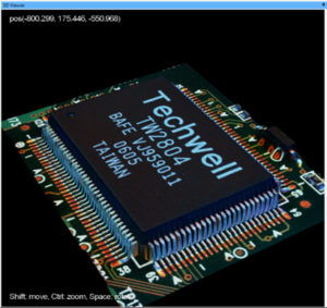
CheckSum test systems are used by the major IC design and assembly companies to test devices such as ICs and sockets for several electrical defects such as opens and shorts, incorrect resistance, capacitance or diode voltage.
The types of devices tested are typically digital ICs with dual, quad, BGA, or Flip Chip CSP (fcCSP) packaging. Since the test system interfaces to the IC with a load board, the system can quickly accommodate virtually almost any device up to 8000, or more, connections.
Rather than rely on TestJet Technology which provides a limited measurement of connectivity, these device test systems use the same test technology and measurements used by the high-performance IC test systems to validate total connectivity.
CheckSum Bed of Nails Device Test System Overview
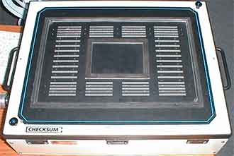
2800 Channel Test Head (load board removed)
The CheckSum test systems are a low-cost production solution for testing even cost-sensitive IC devices. The test system’s small footprint and low power consumption allow these systems to also be used in both lab and cleanroom environments.
The system architecture can be configured with a wide range of channels. Typical configurations support up to 1000 channels, or up to 8000 channels when fully-equipped. The system can be setup to test multiple sites of devices. The high-speed solid-state switching keeps test times low. All test results can be saved for SPC (statistical process control) analysis with the built-in software package. The system login and password protect the test programs from modification by anyone that is not authorized.
The modular architecture scales from desktop test and debug with real-time analysis tools to high-volume, multi-site production on the same test system. The mechanical infrastructure can easily grow to meet your future requirements. The system can be controlled by a handler to automate the change of parts and testing without any operator interaction.
The device test system offers all of this capability with a floor space requirement of less than one meter-square. By contrast, traditional ATE systems require at least four to six times this area to deliver similar capability. The CheckSum system is air-cooled, minimizing HVAC requirements, and uses a standard 115V or 230V outlet.
The system uses a standard Windows PC to control the measurement subsystem. The connection to the DUT (device under test) can be made with a load board or other preferred interface mechanism.
IC Socket Testing
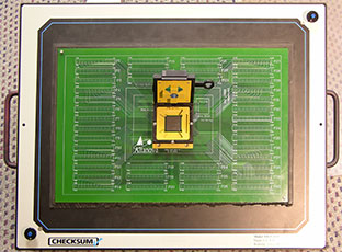
Load board installed with open IC socket, insert and test IC
The test system’s high pin count with very repeatable, low-resistance 4-wire Kelvin tests and auto-learn capability make it ideal for testing IC sockets for opens and connectivity. The system can be interfaced to an automated part insertion handler to automate the insertion and removal of components and testing.
Burn-In Boards
The test system’s high pin count with reliable and repeatable, complex impedance measurements with multiple guard channels plus an auto-learn capability make it ideal for testing all types of boards including burn-in boards. The IC sockets on the burn-in boards require special connections or test type ICs to verify open pins.
Features
Application
Programming CPLDs (Complex Programmable Logic Devices) such as serial flash memories and microcontrollers after these parts have been mounted on the printed circuit board. Since the contents of Phase Change Memory (also known as PCM, PCME, PRAM, PCRAM, and C-RAM) can be lost because of the high temperatures needed to solder the device to a board, on-board programming is required.
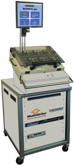
MultiWriter pps™ On-board Part Programming Overview
The MultiWriter pps™ on-board gang programming system uses proven, patented simultaneous programming technology to program up to 384 chips simultaneously, up to 16 different types or families — typically in seconds instead of the minutes required by conventional programmers.
Compared to other part programming solutions, MultiWriter pps delivers significant speed and cost advantages over conventional in-circuit tester-based programmers when more than four parts already mounted on circuit boards must be programmed in a single pass, making it especially effective for multi-board panels.
MultiWriter pps is optimized for applications requiring programming of at least 4 parts per board or multi-board panel. MultiWriter can simultaneously program parts on multi-board panels with 10, 20 or more boards per panel.
Advantages of On-board Part Programming with the MultiWriter pps
Product Details
The MultiWriter pps On-board Gang Programming System includes:
Purchase or Pay-Per-Use
Is Pay-Per-Use the right solution for your programmed parts?
† MultiWriter Technology is protected under U.S. Patent No. 7,802,021.
Programming CPLD (Complex Programmable Logic Device) parts such as microcontrollers, serial Flash and FPGAs after they are attached to the circuit board [’on-board programming’] simplifies the manufacturing process and reduces inventory and rework costs compared to mounting pre-programmed chips.
Since the contents of Phase Change Memory (also known as PCM, PCME, PRAM, PCRAM, and C-RAM) can be lost because of the high temperatures needed to solder the device to a board, on-board programming is required.
Solving the Multi-Board On-board Programming Problem
MultiWriter can simultaneously program parts on multi-board panels with 10, 20 or more boards per panel.
Learn more about Multi-Board On-board Programming
Simultaneous Part Programming
MultiWriter uses patented simultaneous programming technology to simultaneously program up 384 chips at one time, up to 16 different types — usually in seconds instead of the minutes required by conventional programmers.
MultiWriter technology has already programmed millions of parts on millions of boards. Its ability to program up to 384 chips at once makes MultiWriter the industry’s most productive on-board part programmer.
MultiWriter Multiplies Productivity Two Ways
MultiWriter technology is available on CheckSum Analyst low cost in circuit testers or in the new standalone MultiWriter pps™ on-board gang programming system where at least four parts need to be programmed on a board or multi-board panel.
MultiWriter installed in an Analyst series in circuit tester:

MultiWriter pps used following the traditional in circuit tester:
MultiWriter Features & Benefits
MultiWriter technology is a clean, low cost solution to increase part programming productivity–regardless of whether it’s in an Analyst in circuit tester or in the MultiWriter pps gang programming system.
MultiWriter is the first ISP programming system integrated right into the bed-of-nails fixture
Simultaneous device programming
Comprehensive device and bus algorithm library
Unique data may be programmed on a per-device basis — even on panelized boards
Fixture-mounted buffer boards ensure the highest signal quality
¹ Up to 16 MultiWriter control modules with up to 24 buffer modules each for 384 maximum devices. One MultiWriter control module required for each different device type.
† MultiWriter Technology is protected under U.S. Patent No. 7,802,021.
Analyst In Circuit Test Systems
High-coverage In Circuit Test (ICT)
The CheckSum Analyst ems is designed to test all types of circuit assemblies. The system combines manufacturing process testing with TestJet Technology to test a single assembly or a panel of multiple assemblies.
MultiWriter Part Programming
In Circuit On-Board Part Programming

On-Board, Production Part Programming for up to 384 devices simultaneously means high-throughput at low cost.
Reliability at low cost
Reliable low-cost test fixtures from CheckSum.
Turnkey support
Custom fixtures & test programs

Only CheckSum offers complete ready-to-run turnkey applications packages so your boards are in production fast.

The software shipped with every Analyst system includes the Test Executive that runs under Windows OS. The test executive features three primary functions:
Other test executive capabilities include login and password protection to restrict access to specific features of the test station.
CheckSum pneumatic and mechanical test fixtures are rugged, reliable and inexpensive-especially when compared to the heavy vacuum fixtures required by traditional in circuit testers.
CheckSum fixturing is compatible with all of CheckSum’s test systems. Since the electronics are isolated from the fixture you can use CheckSum’s factory-built fixtures or build your own special fixturing or adapters that can accommodate ribbon-cable connectors.
CheckSum can provide fixture kits for your customization or do the complete fixturing and test programming job for you.
Call or e-mail us for a quotation on your next project.
Review the Information Required to Quote and Build Test Fixtures
CheckSum Fixture Selection Guide for EU Member States
CheckSum Fixture Selection Guide for non-EU Member States
Read the FAQs about Fixtures
List of Test Fixture and Spring Probe Suppliers
Model 12KN Dual Level Long-Travel Pneumatic Fixture System
The 12KN Dual Level Pneumatic Fixture System is integrated into a rack-cabinet and designed to be the basis for CheckSum bed-of-nails test systems. The long-travel press eliminates the need to open and close a lid between tests. The fixture kits are easily changed by sliding the fixture top plate and base into place. The system uses a universal spring-probe fixture interface. The fixture system can accommodate up to 5200 test points and uses standard CheckSum fixture kits. Integrated into the system is rack space for system electronics and an operator keypad with a minimum selection of buttons to make it easy, safe, and error-free for the operator to use. The 12KN is compatible with existing CheckSum KIT1000-QC and KIT2KN-QC fixtures. A safety light curtain provides operator safety.
Fixture Guidelines: Assembly size can be up to (approximately) 24 x 13.2 inches (61 x 33.5 cm), dual level, single-sided and double-sided probing plus TestJet.
Model TR-7-1000-QC Pneumatic Fixture SystemThe TR-7-1000-QC is a new version of our popular TR-7-1000 pneumatic fixture receiver. Uses air pressure to press the assembly being tested onto spring probes. Usable to 1000 test system connections, the Model TR-7-1000-QC is ideal for most testing applications including dual-level fixturing. Using low-cost removable fixture kits, it can accommodate assemblies where adding a vacuum seal is difficult.
Fixture Guidelines: Assembly size can be up to (approximately) 16 x 13.2 inches (40.6 x 33.5 cm), dual or single-sided probing and TestJet.
Model TR-5-400-QC Mechanical-Advantage Fixture System
Designed for test fixturing of assemblies with up to 400 test points. The Fixture System consists of a reusable Fixture Press that is used in conjunction with low-cost, easily interchanged Fixture Kits.
Fixture Guidelines: Assembly size can be up to (approximately) 11.75 x 8.5 inches (30 x 21.5 cm), dual or single-sided probing and TestJet.
Model TR-5 Mechanical Bed-of-Nails Fixture Kits
Uses mechanical pressure from the operator to press the assembly being tested onto spring probes. Usable to about 150 test system connections, the Model TR-5 is well suited for applications where vacuum is not available, to minimize cost, or for assemblies where vacuum sealing is difficult.
Fixture Guidelines: Assembly size can be up to (approximately) 14 x 14 inches (35.5 x 35.5 cm), bottom-side probes only.
TR-3-Console Vacuum Bed-of-Nails Fixture System
Console setup for system test electronics to accept industry-standard GR-2270 style test heads with up to 1500 test system connections. Automatic vacuum control and vacuum gauge. Connects to your vacuum source.
Fixture Guidelines: Assembly size can be up to (approximately) 21 x 17 inches (53.3 x 43 cm), single-sided probing and dual or single-sided TestJet.
TR-3A Bench-Top Vacuum Bed-of-Nails Fixture System
Bench-top setup to connect system test electronics to industry-standard GR-2270 style test heads with up to 1500 test system connections. Automatic vacuum control. Connects to your vacuum source.
Fixture Guidelines: Assembly size can be up to (approximately) 21 x 17 inches (53.3 x 43 cm), single-sided probing and dual or single-sided TestJet.
In working with our customers, we have found there are some common questions about bed-of-nails fixturing and test systems. Here are some general guidelines to consider when planning for your test fixture. If you have any questions, call us, we would be happy to discuss your testing needs. Be sure to ask to expedite your job for a faster turnaround.
Fixture FAQs Document (14 pages)
Contents
* Bed-of-Nails Basics
* Customizing the Fixture
* Providing Pneumatic Air Pressure (Analyst / TR-9 / TR-7)
* Providing Vacuum (MultiWriter pps / TR-3 Series)
* Miscellaneous Questions
* Custom test fixtures and test programs from CheckSum
* Fixturing Supplier Source List
* Spring Probe Vendors List
Q. How do „bed-of-nails” fixtures work?
On a bed-of-nails „fixture” or „test head”, the unit-under-test (UUT) is forced onto a number of spring probes („nails”) that are electrically connected to the test system. The test system can then make measurements between these points.
Q. How is the UUT forced onto the nails?
On pneumatic test fixtures, such as the CheckSum Analyst, Model TR-7, and TR-9 series, compressed air pressure and pressure/push rods are used to press the UUT onto the spring probes. On vacuum fixtures, such as CheckSum’s Model TR-3 series, vacuum is used to pull the UUT down onto the probes. On mechanical test fixtures, such as CheckSum’s Model TR-5, the operator presses the UUT down onto the probes via the force of closing the top cover, with pressure/push rods, down on the UUT.
Q. What are the major elements of mechanical, vacuum, and pneumatic fixture systems?
On the TR-5 mechanical fixture, the entire fixture is dedicated for a UUT. The test point electronics from the test system plug into the back of the fixture. On the TR-5-400 / TR-5-600 mechanical-advantage, TR-3 series vacuum, and Analyst / TR-7 / TR-9 pneumatic fixtures systems, there is a fixture receiver (or press) which is shared by all of your UUTs, then a customized „fixture” (or „test head”) is built for each different UUT. The customized test head in the fixture receiver or press is easily changed.
Q. How do I choose between vacuum, pneumatic and mechanical fixtures?
Q. How big a board can I put on a test fixture?
The various size guidelines are shown below. Slightly larger boards may also fit, depending on where the test probes must be positioned with respect to the UUT.
12KN Dual Level Guidelines
KIT28, KIT20, KIT2KN-QC or KIT1000-QC Fixtures: Assembly size can be up to (approximately) 24 x 13.2 inches (61 cm x 33.5 cm), dual or single-sided probes and TestJet.
TR-9-2000-QC Guidelines
KIT2KN-QC or KIT1000-QC Fixtures: Assembly size can be up to (approximately) 16 x 13.2 inches (40.6 cm x 33.5 cm), dual or single-sided probes and TestJet.
TR-9-1000-QC Guidelines
KIT1000-QC Fixtures: Assembly size can be up to (approximately) 16 x 13.2 inches (40.6 cm x 33.5 cm), dual or single-sided probes and TestJet.
TR-7 Series Guidelines
KIT1000-QC, KIT2000-QC or KIT3000-QC Fixtures: Assembly size can be up to (approximately) 16 x 13.2 inches (40.6 cm x 33.5 cm), dual or single-sided probes and TestJet.
TR-5-400-QC and TR-5-600-QC Guidelines
KIT600-QC Fixture Guidelines: Assembly size can be up to (approximately) 11.75 x 8.5 inches (30 cm x 21.5 cm), dual or single-sided probes and TestJet.
TR-5-812 Fixture Kit Guidelines: The kit is 8 x 12 inches (20.3 cm x 30.5 cm) overall and can accommodate an assembly size up to (approximately) 6 x 6 inches (15.24 cm x 15.24 cm) with bottom-side probes only.
TR-5-1216 Fixture Kit Guidelines: The kit is 12 x 16 inches (30.5 cm x 40.6 cm) overall and can accommodate an assembly size up to (approximately) 10 x 10 inches (25.5 cm x 25.4 cm) with bottom-side probes only.
TR-5-1620 Fixture Kit Guidelines: The kit is 16 x 20 inches (40.6 cm x 50.8 cm) overall and accommodates UUT sizes up to 14 x 14 inches (35.5 cm x 35.5 cm) with bottom-side probes only.
TR-5-1612-C Fixture Kit Guidelines: The kit is 16 x 12 inches (40.6 cm x 30.5 cm) overall and accommodates UUT sizes of up to 13.5 x 8.5 inches (34.3 cm x 21.6 cm), dual or single-sided probes and TestJet.
TR-3-2024 Fixture Kit Guidelines: Assembly size can be up to (approximately) 21 x 17 inches (53.3 cm x 43.1 cm), single-sided probes and dual or single-sided TestJet. Smaller vacuum fixture kits are available for smaller boards.
Q. What is involved with customizing the test head for a particular assembly that I want to test?
There are several steps. You start with a mechanical fixture kit (e.g., CheckSum’s Model TR-5-1216), a pneumatic fixture kit (e.g., CheckSum’s Model KIT1000-QC) or a vacuum test head kit (e.g., CheckSum’s Model TR-3-1620), then the steps below are done:
Q. Does the customized part of the fixture have to be done by CheckSum?
No, there are many fixture vendors.
Q. Can I build my own fixtures?
With the proper equipment (e.g., a way to accurately do the drilling), fixtures can be built by the end-user. However, it does require special expertise in many cases to solve some of the problems that can occur. For that reason we recommend that you have at least one fixture built by specialists to serve as an example. You can also contract some of the job, like drilling, then do the wiring yourself.
Q. To test my board, how many probes are required?
Generally, one probe is used for each electrical network (node). As a result, there will be many less probes than there are holes in the board; the node-count is generally about a third of the hole-count. Optionally, you can install extra probes to power supply networks and to very low-impedance value components to help facilitate external sensing of measurements for highest accuracy.
If you want to confirm open connections in PCBs, you will need to use more than one probe per network. This is seldom done in practice since most PCBs are tested prior to assembly and opens typically aren’t caused during the assembly process.
Q. What kind of spring probes should I use?
There are many styles of probes available; many with special attributes for particular applications. The most commonly used probes are some variation of a crown style or chisel style with contact forces of about 6-10 ounces per probe.
Consult the spring probe manufacturers for recommendations on head style and spring force.
Q. Is there anything special to tell a fixturing facility about how to wire a CheckSum test head?
Make sure that they have a copy of CheckSum’s wiring conventions (block and connector nomenclature and pin numbering scheme). We will provide this information directly to the vendor if you wish. For GenRad-style vacuum fixtures, the test head is oriented with the interface towards the operator, so the UUT orientation is generally reversed from GenRad fixtures.
If you are fixturing for functional test, there are some special wiring considerations. See the Model FUNC-2 Instruction Manual for details.
Q. How large must the vacuum test head be?
The outside dimensions of the test head need to be at least 3 inches (7.6 cm) larger than the UUT (1.5 inches, 3.8 cm, all around). The most popular sized vacuum test head that CheckSum sells is the TR-3-1620, 16 x 20 inches (40.6 cm x 50.8 cm) overall. Both smaller and larger test heads are available. CheckSum lists the sizes of our test heads in overall size. Some other manufacturers list the working area. Make sure to ask the supplier if there is any question about their dimension conventions.
Q. I need a small amount of special circuitry to help test my UUT. Can this be accommodated?
There is sufficient room in most test heads to accommodate internal circuits like relays or breadboards. CheckSum offers the Model TR-6-2 Interface Module especially designed for this use.
Q. I will be testing surface-mount boards. Can they be used with a bed-of-nails fixture?
For the lowest cost fixture, lay out the PCB so that there is access from one side of PCB to at least one point on every network (net). Careful placement of through-holes can usually provide this. With this layout, you can test using a standard test head. Recommended target pad size is .035 inches (0.89mm) or larger. If you require probe access to both sides, special double-sided fixtures can be built. Double-sided fixtures are very common with SMT boards however they are more expensive. See the following reference at the SMTA web site for DFT guidelines: http://www.smta.org/store/book_detail.cfm?BOOK_ID=176
Q. My UUT has test points on both sides (top and bottom). Can CheckSum probe both sides of my UUT?
CheckSum has been making dual-sided “clamshell” test fixtures for many years. Our pneumatic fixtures and presses are well suited for top probing of fixtures. For top probing, it is important to provide good size test pads for better probing accuracy.
Q. Are there any other PCB layout considerations?
Fixturing is more reliable and less expensive if holes are on 0.1 inch (2.54 mm), or greater, centers. Probes are available for closer spacing, but the fixturing job is more difficult since closer positioning tolerances are necessary, and the probes are more expensive. The 50-mil and 75-mil probes are very common on the high-density SMT boards we see today. Also, for vacuum fixtures, keep component leads at least 1/8 inch (3.175 mm) from the board edges.
Providing Pneumatic Air Pressure (Analyst / TR-9 / TR-7)
Q. What kind of air supply is necessary for pneumatic fixturing?
Standard factory air can be used in most cases. The fixture operates from 80-120 PSI. Use of a standard regulator/filter near the test system is recommended.
Refer to the specific fixture system manual. The higher force spring probes will require greater force to fully-compress. This may require the maximum air pressure; 120 PSI for some test fixtures.
Providing Vacuum (MultiWriter pps / TR-3 Series)
Q. How much vacuum do I need?
Most vacuum test heads require about 20 inches of mercury (67.75 kPa) with a 20 gallon vacuum surge tank (vacuum reservoir) to work properly. Pumps with this capacity are generally 1.5 HP and larger.
Q. Does my particular UUT affect the amount of vacuum needed?
Yes. UUTs that have many probes per square inch of PCB area may require more vacuum force. Generally, vacuum requirements start to become more critical if the average probe loading of your UUT exceeds about 10 probes per square inch of PCB area. Also, if your UUT has openings that can’t be sealed with a gasket (e.g., open vias or routes), or if it has unsoldered through-holes, it may require more vacuum CFM capacity.
Q. Does it help to get a bigger pump?
Since the incremental cost of purchasing a larger pump is relatively small, we recommend getting one bigger than you need. That way, if you add systems in the future and want to share a pump, or if you have a problem UUT requiring additional capacity, you will be ready.
Q. Is a vacuum pump all I need?
You should also have a vacuum surge tank to accommodate the initial vacuum requirement when pulling the UUT down to the fixture.
The vacuum hose connected to the MultiWriter pps or TR-3 series should be large enough to quickly and completely pull the board down on the spring probes.
If the vacuum source is not sufficient, when the vacuum is applied the UUT will not be pulled-down quickly. It needs to be quickly pulled-down to create a vacuum under the UUT to seal the UUT with the gasket. As the UUT moves down, it will compress the spring probes that need to firmly contact the UUT.
Q. Are there alternatives to the surge tank?
Some facilities use large PVC tubing (e.g., 2 to 3 inches, 5 to 7.6 cm, diameter) for plumbing the vacuum system. If properly designed, this can effectively serve as a surge tank.
Vacuum surge tanks are generally 10 gallons or larger.
Q. Can I buy the vacuum pump from CheckSum along with the system?
CheckSum can sell you a vacuum pump along with your system. However, you can save money by buying it directly from the manufacturer. If purchased from CheckSum, we will have the manufacturer ship it directly to you.
Q. Can you give a recommendation for a vacuum system?
Most ATE systems use Busch brand vacuum pumps. An example of a complete 28 CFM system with motor, pump, tank, filters, hose, skid and casters is the Busch BMV-040-0. A similar 20 CFM system is Busch’s model number BMV-025-0. Busch pumps use 3-phase power.
Q. How much does a vacuum system cost?
For a typical installation, you should plan on about $2500 to $3500 for a vacuum system.
Q. I’ve got a bunch of fixtures for my old worn-out system that was made by *%@!#!*%*. Can I use them?
There is nothing unique about CheckSum testers that makes fixturing special. If you can adapt your existing fixtures to mate with the 50-pin ribbon cables from the CheckSum System, you’re in business. Fixture manufacturers (or CheckSum) can also build adapters from one type of fixture to another type of receiver.
The Analyst fcs (fixture compatible series) is specifically designed to accept Agilent 1, 2 and 4 module 3070 style fixtures. The test system software includes a test program generator to automatically create the CheckSum test program using existing 3070 data files.
Q. Is there a way to take advantage of the CAD data I have to help with fixturing and programming?
Yes. CheckSum provides CAD conversion capabilities with its in-circuit test systems. Also, third-party software packages can help lay out the fixture and provide an initial test program. Please review our document on the Information Required to Quote and Build Test Fixtures.
Q. My UUT is not designed for test. Can CheckSum probe on SMT components to improve my test coverage?
Probing on components is a risky practice. The only way to probe SMT parts directly is to probe on the solder fillet. This presents (3) main problems:
It is CheckSum’s practice not to probe on components. Please review our design for test document.
Q. I have multi-board panels. Can these be tested before separation?
Yes. They are fixtured just like a single assembly. It you arrange the wiring properly, CheckSum in-circuit test systems allow you to create the test program for the first PCB on the panel, then automatically replicate the test for the remainder of the PCBs. The system also automatically separates test results as appropriate, allows you to skip particular PCBs on the panel, and shows which PCB is being tested.
With panelized PCBs, it is good practice to also provide a single test position to accommodate testing assemblies after separation after they have been repaired.
Please include drawings that show the dimensions for each separate board on the multi-board panel. We need each board’s specific XY information to position the spring-probe and guide pin locations.
Custom test fixtures and test programs from CheckSum
CheckSum can do custom programming and fixturing for you. We recommend that you have us build your first fixture and write the test program used with it to serve as an example and to make sure that you are up and operating right away. Many of our customers continue to have us build their fixtures and write their test programs on an ongoing basis. Call us for a quotation for your next CheckSum fixture project.
Q. If I am going to have a test head built, what do I need to provide?
You will need to provide complete CAD* information (ASCII full CAD output, gerber files and a drill file), a mechanical drawing that calls out board dimensions, a schematic, a BOM (Bill of Materials) an assembly drawing showing component placement, a bare-board, and a loaded-board.
*Note: Jobs can be processed without full CAD data in some situations, but the costs are much greater and the lead time is increased. If you also provide information directly showing the XY position of each probe and an associated net-list or annotated schematic, it reduces the cost of the job.
Q. I plan to write the test program, can you give me a budgetary cost estimate for building a custom bed-of-nails fixture for my assembly?
The cost varies, but here is a rough idea of what to expect:
Test fixture kit: $610 – $870
Drilling, file-processing, machining: $750
Wiring connectors: $10 per 50 probes
Probes, sockets, layout, wiring: $3.00 – $6.00 each
Based on this, here is a general idea of what you might expect to pay for mechanical or pneumatic fixtures of various sizes (assuming only 100-mil probes are required):
100 Test points: $1,850
250 Test points: $2,300
500 Test points: $3,500
Vacuum fixturing costs are similar, but higher. With additional vacuum sealing costs and higher fixture kit costs, typical vacuum fixtures are about $1000 more than the alternatives shown.
Q. If CheckSum is going to write the test program, is there anything else I need to provide?
We need at least 2 or 3 (the more the better) known-good sample assemblies to validate the test program. After programming, we run statistical analysis on all the assemblies to help determine proper test tolerances to accommodate typical UUT-to-UUT and measurement variations. If you have compatible CAD data for the UUT (netlist and component values), it can be used to reduce the cost of programming.
Q. Can you give me a rough idea of how much it will cost to have CheckSum write the in-circuit test programs for my assemblies?
In-circuit test programming charges vary depending on the type of circuitry and node-count. The minimum programming charge is $600 ($300 for Opens/Shorts only).
Here is a general idea of the cost for a complete turn-key test fixture which includes the in-circuit test program for various test point counts:
100 Test points: $2,500
250 Test points: $4,000
500 Test points: $6,000
For panels with duplicate boards the programming cost goes down significantly.
Q. Does TestJet Technology drastically affect the costs of my fixtures?
Installed TestJet Technology probes cost about $100 per tested component. There usually is an additional fixed charge of about $450 for the top-access assembly that positions the probes. Note that CheckSum’s TestJet Technology implementation does not require a multiplexer to be built into every fixture. That is part of the test system.
Q. What are some of the things that affect fixturing/programming costs?
Q. Does CheckSum do this work for „time and materials”, or can I get a quote?
We do most of our work on fixed-price quotations. To give you a quotation, we need to know the probe-count (available from a net-list), any special probe spacing requirements (usually not a problem on through-hole or designed-for-test SMT boards), the UUT size, and the type of circuitry (digital vs. analog as shown in a schematic). If you provide us with this information we can usually give you a quote within 24 hours.
Q. How long does it take CheckSum to build a custom test fixture and test program for my UUT?
Standard lead-time is three to four weeks from the time we get your order and UUT materials. We can often do a faster turn around if you are willing to pay expedite fees.
Q. Is there anything special about the mechanical design of PCBs that will be bed-of-nails tested?
There are a number of things that you can do to optimize test coverage and fixture reliability while minimizing cost.
Q. Can CheckSum start my job without a loaded assembly?
To insure the fixture matches your assembly, we need a loaded assembly before we start the process. Ask for our paper on Design and Building Custom Test Fixtures for details about what we need for quoting and building your test fixtures. We can provide quotations for fixtures with or without a test program. In some instances, it is possible to get started with a new revision bare board, the most recent revision loaded board, and a list of the affected changes between the revisions. CheckSum will need to review the two (2) boards to determine if the job can be scheduled. You will still need to provide the current revision loaded board by a specified date to have your fixture and test program fully optimized.