


The high-throughput option uses a dual test system architecture with dramatic results.
Benefits and Features
2 x Faster for multi-up panels
Use existing fixtures with minimal wiring additions
Compatible with existing Analyst series test systems
Upgrade your Analyst series In-Line, TR-9, & 12KN test systems
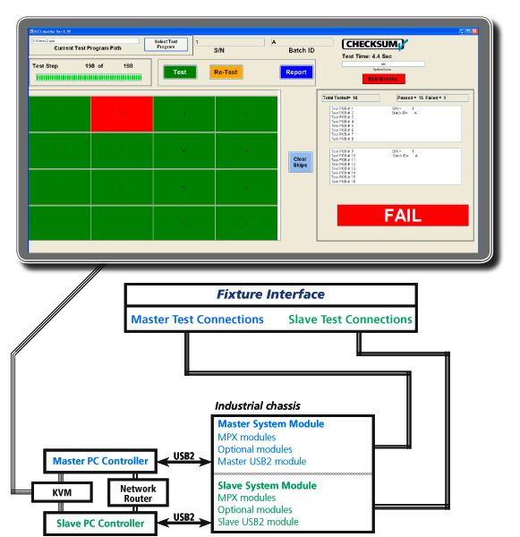
Please contact CheckSum to discuss the high-throughput option as an upgrade to your CheckSum, or with a new test system.
† MultiWriter Technology is protected under U.S. Patent No. 7,802,021.
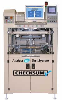
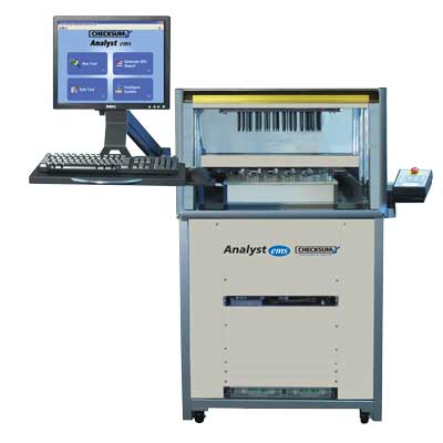
Designed for testing all types of circuit assemblies the CheckSum Analyst ils has all the features of the Analyst ems, but in a package with an integrated high-speed board handler for use in an automated production and test line. The CheckSum Analyst ils combines manufacturing process testing with TestJet Technology for high fault coverage in circuit test of a single assembly or a panel of multiple assemblies in minimum time with maximum fault coverage.
Providing features such as periodic sampling of UUTs passing down the line and automated recompression of probes and/or automatic retesting on failures, the Analyst ils meets sophisticated testing needs.
The Analyst ils performs effective power-down testing for most analog or digital assemblies being manufactured today quickly and easily testing through-hole and SMT circuit board assemblies for common manufacturing defects such as incorrect, missing or misoriented components, and opens and shorts. Equipped standard with TestJet Technology, Analyst can identify opens in and around most analog and digital IC packages. These faults comprise the vast majority of problems encountered in the today’s electronics manufacturing environment.
The optional power-up functional test capability is ideally suited for lower frequency analog assemblies with some digital content.
The Analyst ils tests the entire unit-under-test (UUT) and individual components without power applied to the UUT. Using sophisticated measurement techniques such as DC or complex-impedance measurements in conjunction with multi-point guarding, ICT systems quickly and accurately measure continuity, capacitors, resistors, inductors, voltages, semiconductor junction voltages, and SMT connections for opens. By finding the majority of faults while the UUT is in the safe unpowered mode, together with very specific fault diagnostic messages, faulty UUTs can be repaired quickly.
| There are two versions of the Analyst ils handler; standard and -43. The standard model accommodates boards up to 340mm by 254mm (13.4 inches wide and 10 inches deep). The -43 model is designed to accommodate boards up to 400mm by 300mm (15.7 inches wide and 11.8 inches deep). |
The Analyst ils is designed to SMEMA standards for straightforward integration into your production or testing line. The standard configuration is complete for most testing operations and features safety interlocks essential to automated operation.
CheckSum can ship the system to you complete with a ready-to-use test fixture and test program for one or more of your UUTs. You can use CheckSum’s fixturing division to handle all of your fixturing and programming needs; or you can modify or add UUTs yourself or with the use of third-parties.
To configure the system for testing, easily removable, cableless fixture kits are installed without the need for tools. Test fixture change-over takes only a few seconds.
The system uses the SMEMA signals to automatically signal a loader, move the assembly into the testing position, test the assembly, and unload each assembly without an operator. Once the test is completed, the system displays the results. The system can be configured to automatically produce a test report, or can be setup so that results are saved for statistical analysis (SPC) with the included software.
The optional offline test development station is used for test fixture development and program debug. Instead of taking valuable production time from the Analysis ils, this lower cost station is used. The offline test development station is designed to use the KIT2000-ILS-43 fixture kits, compatible with the -43 version of the Analyst ils.
The offline development station will need the same test resources (test modules, power supplies, etc) available in the Analyst ils system. Unlike the Analyst ils, the offline station requires an operator to load and unload boards. For safety, back and side panels are provided to keep objects away from the moving parts and the front panel operator buttons require two-hands to lower and raise the top lid.
For component in circuit testing, the Analyst system provides effective tools to find most faults. These measurements are made with signal injection/measurement, but without the UUT powered-on — greatly simplifying test programming and — reducing ongoing application cost. Measurements are taken at high speeds using a solid-state multiplexing system.
Opens/Shorts
Analyst can test from each point to each other point to detect faults. Open/short thresholds are typically in the 10 ohm range, but can be programmed over the range of 2 ohms to 50Kohms. Continuity tests can use 10mA, 1mA or 100µA source current. Specified pairs of points can be designated as „no-cares” to allow the most effective diagnostics or to deal with points that are near threshold values.
Resistance Measurements
Analyst provides the ability to measure from 0 ohms up to 19Mohms using various techniques to optimize the measurement effectiveness. You can choose between using a constant-current source (0.1µA to 10mA), a DC constant-voltage source (.02V to 2V full range), or AC complex-impedance measurements over the range of 100Hz – 1KHz. Resistance tests can be used with external sense (4-wire Kelvin measurements), and in conjunction with multi-point guarding to isolate individual components. Guard currents up to 100mA are available. Up to 16 distinct measurement and stimulus functions can be active during a single measurement.
Capacitance Measurements
Analyst provides the ability to measure from a few pF up to 20,000µF. You can choose between using a constant-current pulsed source (1mA to 10mA), or AC complex-impedance measurements over the range of 100Hz to 100KHz. Capacitance tests can be used with external sense (4-wire Kelvin measurements), and in conjunction with multi-point guarding to isolate individual components. Guard currents up to 100mA are available. Up to 16 distinct measurement and stimulus functions can be active during a single measurement.
Inductance Measurements
Analyst provides the ability to measure from a few µH up to 1000H. Measurements are made by using complex-impedance measurements with stimulus frequencies between 100Hz and 100KHz and full-range amplitudes of .02V to 2V. Inductance tests can be used with external sense (4-wire Kelvin measurements), and in conjunction with multi-point guarding to isolate individual components. Guard currents up to 100mA are available. Up to 16 distinct measurement and stimulus functions can be active during a single measurement.
Voltage Measurements
For UUTs that have batteries, DC amplitudes up to 10 volts can be measured. Fully differential measurements can be made up to ±8V from chassis ground.
Transistors
Transistors can be tested as two diode junctions, or tested for Beta while in circuit. The Beta test can help determine proper insertion polarity for transistors that can be installed backwards, but with the base still in the middle. This type of fault cannot typically be detected with diode testing of the junctions.
FETs
FETs can be tested for turn-on voltage. By sweeping a voltage into the gate while monitoring the Source/Drain impedance, the FET can be checked for proper orientation and operation.
Opto-Isolators
Opto-isolators can be tested by sourcing into the input leads while measuring the output impedance. By testing each device in the on and off state, high confidence is obtained.
Relays
Up to 24V with up to 100mA can be used to actuate relay coils. This allows testing of contacts in each state to ensure that the contacts are not shorted, and that the coil is operational.
Diodes
Diodes are tested by providing a constant current source (0.1µA to 100mA), then measuring the forward voltage drop, which is typically in the 0.6V to 0.8V range. This test ensures that the diode is installed, is in the proper orientation, and is not open or shorted.
Zener Diodes
Zeners are tested by providing a constant current source (0.1µA to 100mA), then measuring the forward voltage drop. Measurements up to 50V can be performed. This test ensures that the zener diode is installed, is in the proper orientation, and is not open or shorted. Zeners that cannot be brought to their full voltage due to current or voltage limiting can be tested as normal diodes or in some cases can be tested during the power-up stage.
LEDs
LEDs are tested like signal diodes, but normally have higher forward voltage drop. Special light-sensing probes can be added to customized test fixtures to detect brightness and color of LEDs and incandescent lamps.
Transformers
Transformers are typically tested for dc resistance of each coil to detect presence. Coils can also be tested for inductance, and a polarity test can be used to ensure that each coil is wired correctly. This can detect faults inherent to hand-loading of transformers with wire leads.
IC Presence/Orientation
IC’s are tested by using the ICs test. This test measures each IC pin to specified pins such as VCC, VSS or VDD, checking for the presence of the IC’s internal protection diodes. This test detects most faults such as shorted pins, open pins or mis-clocked or wrong ICs. In some cases, faults may not be detected if the IC pins are bussed or devices of similar pin-topology are interchanged.
IC Pin Connections
With the use of TestJet Technology, Analyst can detect opens to IC pins, even though the pin is bussed to other ICs. This advanced technology (licensed to CheckSum by Agilent), uses a sophisticated software/hardware algorithm to measure the minute capacitance between the PCB and the IC for each pin. If a pin is open, the capacitance significantly decreases. This technology can be used for most non-power and ground lines on the ICs and on many connectors to ensure proper connection and/or presence of the connector.
Capacitor Polarity based on TestJet Technology
In some cases, constant-current and voltage measurements of a polarized capacitor can be used to detect incorrect polarity since the capacitor draws additional current as the voltage increases in the incorrect polarity. As a practical matter, this technique cannot be used in many cases during in circuit testing because of voltage or parallel impedance limitations. In this case, the SMT option can be used to detect the polarity of most axial/SMT aluminum and tantalum capacitors up to about 200µF.
Power Module
The Analyst system includes a power module that can be used to provide higher current outputs to actuate UUT relays, power-up low power UUTs, provide additional guard current, or apply stimulus for power-up testing. The module has dual voltage-programmable high current outputs that can be set from +12V to -12V (up to 24V differential). For switching these outputs to the UUT, 16 relay test point outputs are provided. Voltage and current output can be monitored. Fixed switched supplies provide +12V, +5V and -12V at the back panel. These outputs can be switched on or off via on-board relays. The outputs are fused for protection of the system and UUT. Eight additional digital pins can be used for digital input/output or to energize external relays.
Digital I/O Option
Analyst can be configured with an optional 48 or 96 digital I/O pins. These pins can be relay-connected to the UUT in byte increments. Within each byte, each pin can be set to be an input (tri-state output) or an output. Since each pin has a 10KW pull-up (in conjunction with totem-pole outputs), it is compatible with most logic families. VCC for output can be selected to be +5V or +3.3V.
Boundary-Scan Option
The Analyst ils can be configured with the optional Boundary-Scan Test. This allows the System to be used with UUTs that have been designed to accommodate boundary-scan, or have on-board devices that support boundary-scan. In addition, boundary scan can be used by some programmable devices to perform in-system programming and program verification.
MultiWriter ISP Device Programming
The Analyst ils can be equipped with the MultiWriter ISP programming and verification capability to simultaneously program up to 384 ISP devices in circuit.
Other System I/O
In addition to the power/stimulus/measurement capabilities already mentioned, the System has a number of other functions available. These include 8 bits of Digital I/O / Relay drivers (PWR-2) and 2 Switched grounds (PWR-2)
System Switching Topology
Analyst offers a flexible switching topology to minimize custom circuitry and to allow assemblies to be easily programmed.
The system uses an N x 16 solid-state analog bus that allows each test point to be a measure source high, measure source low, measure sense high, measure sense low, guard source, guard sense, or DC/AC signal source. The solid-state matrix provides high-speed and reliability for power-down testing, or for functional testing of points that do not exceed ±12V referenced to the computer chassis.
A 16 x 2 relay matrix is also included for signals in excess of 10mA, or for voltages greater than ±12Vdc (i.e., Zener measurements).
Digital test points are available at the fixture interface blocks. They can be relay-disconnected during power-down test, then enabled (by byte) during power-up test.
Power outputs are available at the fixture interface blocks. They can be relay disconnected during power-down test. This includes the ground signals so that the UUT is fully floating.
Test Fixturing
The Analyst ils includes a pneumatic fixture press built into a rack-cabinet. This unit can be installed on your factory floor, and is ready for use once connected to standard compressed air and an AC outlet. The standard configuration is complete for most testing operations and the SMEMA signals integrate the unit into the automated line.
CheckSum can ship the system to you complete with a ready-to-use test fixture and test program for one or more of your UUTs. You can use CheckSum’s fixturing division to handle all of your fixturing and programming needs; or you can modify or add UUTs yourself or with the use of third-parties.
The optional CheckSum fixture kit, KIT2000-ILS-43 or KIT2000-ILS-QC, is low-cost to minimize your recurring costs. Installing the fixture kit simply involves locking the top and bottom units into place. The bottom assembly includes a fiberglass probe plate with a fixture interface section. The top assembly is a clear polycarbonate plate that is used with pressure rods to press the UUT down onto the spring-probes. It can be machined and milled with openings to allow for tall components.
To run a test, the system signals the upstream loader that the system is ready. Once the UUT enters the loading area, a conveyer automatically moves the UUT into position to be tested. The system lowers the UUT onto the spring-probes, the top moves down to compress the spring-probes and the test begins. Once the test completes, the system prepares the UUT to exit, waits until the unloader is ready, signals a Pass or Fail to the next system in-line and moves the UUT onto the unloader. Once the test is completed, the system displays the results.
The typical Analyst ils test system consists of a complete, ready to use, 800 test point system with:
The Analyst ils system can be configured with additional modules and other options that can expand the system:
If you need a different configuration, feel free to call us and discuss your application.
Features
Applications
Analyst ems+ft In Circuit Test Overview
The CheckSum Analyst ems+ft extends the testing power of the Analyst ems with an integrated functional test subsystem that includes flexible stimulus, measurement and switching capabilities. It combines in circuit test (ICT) with power-up functional test to provide high fault coverage in a single, low-cost platform that can be customized by the user to fit a variety of test requirements.ÂÂÂ
Including industry-unique features such as 250VAC switching and a fully integrated DMM, function generator and counter-timer, as well as available relay switching in 50 point increments, the Analyst ems+ft meets a broad range of functional test requirements from straightforward power up „board alive” tests to extensive functional test sequences.
A typical test sequence on the Analyst ems+ft would proceed as follows:
Solid-state switching in 200-point increments and 50-point relay switch matrix cards may be mixed in any combination.
Circuits with voltages up to about ±12V will typically employ solid-state switching and voltages up to 250Vp-p are accommodated by relay switching. When greater than 40 volts is present at the UUT during test, the test fixture should be designed with safety shielding and operator interlocks to help prevent the operator from coming in contact with the signals.
In most cases functional test can be performed using the same test fixture as the in circuit test so that minimal time is spent transferring, loading and unloading the UUT.
The Analyst ems+ft includes an additional 19 inch rack space, allowing addition of off-the-shelf measurement/stimulus instruments or programmable power supplies to meet special requirements.
Functional Test Capabilities
The CheckSum FUNC-2 board is at the heart of the Analyst ems+ft system and provides the capabilities used for a wide range of functional testing requirements:
For unique or more sophisticated functional testing needs, the System can control GPIB instrumentation via an IEEE-488 controller.
Analog Measurements
DC Volts
The system can measure up to 250VDC. Measurements are made in a fully differential input mode up to 250V. Ranges include 0.2V, 0.6V, 2V, 6V, 10V, 20V, 60V, 200V and 600V (rated to 250V) and auto-range.
AC Volts
The system can measure up to 250VRMS. These true RMS measurements are provided with AC or AC+DC coupling. Ranges include 0.2V, 0.6V, 2V, 6V, 20V, 60V, 200V, 600V (rated to 250V) and auto-range.
Frequency
Frequency measurements can be made from DC to 10MHz. Higher frequencies can be performed if the test fixture includes a pre-scaler. The ground-referenced input can be from 300mV to 5V, and can be AC or DC coupled. The trigger level can be set in the range of ±2.2V.
Period
Period measurements can be made from 12.8 milliseconds to 128 seconds. The ground-referenced input can be from 300mV to 5V, and can be AC or DC coupled. The trigger level can be set in the range of ±2.2V, and can be set to respond to rising or falling transitions. Period measurements can be made with A and/or B inputs.
Counts
Counts can be made of up to 65,535 events based on the trigger event occurring. The ground-referenced trigger input can be from 300mV to 5V, and can be AC or DC coupled. The trigger level can be set in the range of ±2.2V, and can be set to respond to rising or falling transitions. Up to 5MHz signals can be counted.
Stimulus Capability
DC Volts
The System has three DC voltage signal sources, each of which can source up from ±10V, and providing up to 10mA of current. These sources are internally sensed.
Sine Wave
The System can provide sine wave output in the range of 100mV to 20Vp-p (7VRMS). The frequency selection range is 1Hz to 50KHz. Sine wave output is ground referenced and can provide up to 10mA of output.
Square Wave
The System can provide square wave output. Amplitude can be ground-reference to ±10V, or can be between two programmable amplitudes each from ±10V, with up to 10mA. The frequency selection range is 1Hz to 50KHz.
DC Current
The System provides two 100mA current sources with programmable voltage. Each source can be programmed to a compliance voltage between ±12V. When used together, the sources can provide up to 24V differentially.
Digital I/O
The standard configuration of the Analyst ems+ft includes 96 digital I/O pins. These pins can be relay-connected to the UUT in byte increments. Within each byte, each pin can be set to be an input (tri-state output) or an output. Since each pin has a 10K ohm pull-up (in conjunction with totem-pole outputs), it is compatible with most logic families. Logic high output can be selected to be +5V or +3.3V.
Boundary-Scan
The Analyst ems+ft can be configured with optional Boundary-Scan Test. This allows the System to be used with UUTs that have been designed to accommodate boundary-scan, or have on-board devices that support boundary-scan. In addition, boundary scan can be used by some programmable devices to perform in-system programming and program verification.
MultiWriter† In Circuit Part Programming
The Analyst ems+ft can be equipped with the MultiWriter in circuit part programming and verification capability to simultaneously program up to 384 devices in circuit.
In Circuit Tests
Measurement Capabilities
Even though CheckSum in circuit systems are truly low in cost compared with alternatives, they provide extremely sophisticated measurement capabilities. You can choose from several basic techniques to achieve the best in circuit measurement results. Measurements use DC current or AC/DC voltage as measurement stimulus.
Resistance, Capacitance and Inductance Measurements
Current-based measurements are performed by applying a DC constant-current through the component being measured, then measuring the resultant voltage drop. For current-based capacitance measurements, the system measures the rise-characteristics of the developed voltage over time to determine the capacitance value. DC voltage-based measurements apply a voltage to the component being measured, then measure actual voltage across the component and the current that passes through it.
When AC voltage-based complex-impedance measurements are made, the system applies the signal, then measures the in-phase and quadrature-phase voltage and current. From these, the capacitive, inductive and resistive components of the measurement are determined.
By choosing from alternative frequencies, the impedance of the measured component can be optimized compared to parallel impedances for best measurement results.
In some cases, capacitor polarity can be tested by applying current-limited DC to the capacitor and measuring the voltage across the capacitor. A lower voltage is developed if the capacitor is installed incorrectly.
To eliminate the effects of path resistance internal to the tester and in the fixture wiring, measurement points can be externally sensed, providing 4-wire Kelvin measurement capability at the UUT rather than internal to the tester. This helps increase the accuracy of low impedance measurements.
To prevent semiconductors from turning on during the measurement, you can choose a 20 or 200mV full range stimulus in place of the standard 2V stimulus. AC measurements can be biased to prevent interference from parallel diodes in the measurement path.
Guarding
In circuit measurements often contain parallel impedances that can cause measurements to deviate from component nominal values.
Guarding provides the capability to minimize the effects for parallel impedance paths. Guarding uses special sense and drive circuitry to source or sink current into other UUT circuit nodes to eliminate current flow through these paths.
CheckSum Analyst systems allow you to specify multiple guard points during a measurement. Guard points can be externally sensed to provide additional guarding accuracy when low impedance paths exist. Any test point can be used as a guard point. No special wiring is required.
Unlike other solid state switch-based in circuit test systems, CheckSum uses separate guard drivers for each of its guard points. This additional sophistication can provide the proper guard voltage at each guard point, regardless of connection impedance differences.
Even without guarding, Analyst systems can usually directly measure components of different types connected in parallel, such as a capacitor and a resistor, with the use of complex-impedance measurements.
Transistors and FET Testing
Three-terminal devices such as transistors and FETs are tested by measuring between the current-carrying terminals while biasing the control terminal. FETs are biased with voltage, while transistors are biased with current.
Opto-Isolators
Opto-isolators can be tested by sourcing into the input leads while measuring the output impedance. By testing each device in the on and off state, high confidence is obtained.
Diode Testing
Diodes, LEDs, zener diodes and transistor junctions are tested by applying a constant-current, then measuring the voltage dropped across the device.
IC Presence and Orientation Testing
IC presence and orientation is verified by checking the semiconductor junction voltage of the protection diodes typically present between IC pins and the UUT power supplies. This mapping is self-programmed from a known-good UUT.
Opens and Shorts Detection
Since most faults that occur during manufacturing are shorts, MDAs provide the ability to perform continuity testing for opens and shorts. The systems self-learn the continuity map of a known-good UUT, then test against this map for other UUTs. Selected open/short measurements can be ignored to prevent testing of components near the continuity threshold or to provide better diagnostics with separate measurements.
Using TestJet Technology*, Analyst in circuit test systems can find open connections to surface-mount technology (SMT) devices such as ICs and connectors.
Relay Testing
Up to 24V with up to 100mA can be used to actuate relay coils. This allows testing of contacts in each state to ensure that the contacts are not shorted, and that the coil is operational.
Transformer Testing
Transformer coil presence can be tested with resistance and/or inductance measurements. CheckSum MDA systems can also test the polarity of transformer connections to ensure that they are correct. Since transformers are often hand terminated, this will find faults not detected by normal coil resistance testing.
TestJet Technology
A common fault in surface-mount technology manufacturing is open connections. On components with bussed connections or high impedance pins, these faults cannot be detected by normal analog in circuit measurements. Analyst in circuit testers allow you to detect these faults using award-winning TestJet Technology. A flat probe is built into the fixture over each component body to be tested. The system measures from this top probe to each signal pin on the SMT device. By measuring precise capacitance values (in the fF region) the system detects open connections. This technology works for most SMT ICs and connectors.
Capacitor Polarity based on TestJet Technology
In some cases, constant-current and voltage measurements of a polarized capacitor can be used to detect incorrect polarity since the capacitor draws additional current as the voltage increases in the incorrect polarity. As a practical matter, this technique cannot be used in many cases during in circuit testing because of voltage or parallel impedance limitations. In this case, the SMT option can be used to detect the polarity of most axial/SMT aluminum and tantalum capacitors up to about 200µF.
Power Supplies
The Analyst ems+ft system power supply options can be used to power-up your UUT:
PS-UUT-L2 Power Supply option
2 programmable supplies, 0 to 60 VDC, up to 12.5A each
Accuracy:
Voltage Output: 0.05% of Vout + 30mV
Current Output > 50mA to 12.5A: 0.10% of Iout + 25mA
Current Output < 50mA: 0.10% of Iout + 50mA
System Configuration
Mechanical Format
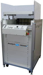
The Analyst ems+ft 12KN includes the 12KN dual-level, long-travel pneumatic fixture press built into a rack-cabinet. This unit can be installed on your factory floor, and is ready for use once connected to standard compressed air and a 220VAC outlet. The standard configuration is complete for most testing operations. It requires only one load/unload cycle per test, with no lids or doors for the operator to manipulate between tests. CheckSum can ship the system to you complete with a ready-to-use test fixture and test program for one or more of your UUTs. You can use CheckSum’s fixturing division to handle all of your fixturing and programming needs; or you can modify or add UUTs yourself or with the use of third-parties.
Fixture Kits
The optional CheckSum fixture kits; KIT28, KIT20², KIT2KN-QC², or KIT1000-QC² can minimize your recurring costs. The fixtures include handles to make storage and moving easy. Installing the fixture kit simply involves sliding the top and base into place. The bottom assembly includes a fiberglass (G-10 / FR4) probe plate with a fixture interface section and pan covering the wiring.
The top assembly is a clear polycarbonate plate that is used with pressure rods to press the UUT down onto the spring-probes. The top assembly can be machined and milled. The front of the UUT is accessible during test time for adjustment access.
To run a test, the operator places the UUT on the fixture guide pins, then presses the start test button. Once the test is completed, the system displays the results and the fixture top automatically rises so the UUT can be removed.
The configuration of the Analyst ems+ft 12KN as a complete, ready to use, 400 test point test system:
If you have a special test requirement and need a different configuration, feel free to call us and discuss your application.
† MultiWriter Technology is protected under U.S. Patent No. 7,802,021.
* TestJet Technology is protected under U.S. patent numbers 5,124,660 and 5,254,953.
¹ The compression force required for the total number of spring-probes cannot exceed the 2700 pounds (12000 newtons) limit of the 12KN system.
² An adapter is provided to use KIT20, KIT2KN-QC, or KIT1000-QC fixtures on the 12KN. Existing KIT1000-QC and KIT2KN-QC kits may require top plate modification.
Features
Applications
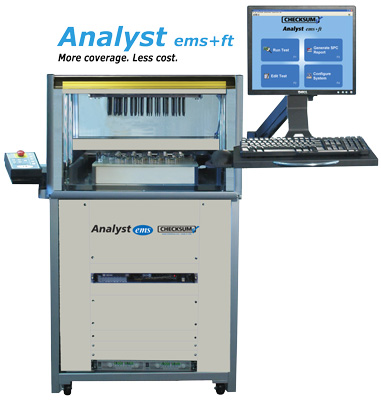
Low-Cost In Circuit Test Overview
The Analyst ems Low-Cost In Circuit Test (ICT) System provides the capability to quickly and easily test assemblies for common manufacturing defects such as incorrect, missing or misoriented components, and opens and shorts. These faults comprise the vast majority of problems encountered in the typical manufacturing flow. ICT systems can quickly and accurately measure continuity, capacitors, resistors, inductors, voltages, semiconductor junction voltages, and SMT connections for opens. With these basic tools, ICTs can find most faults in analog or digital assemblies before board power-up.
The CheckSum Analyst ems is designed for testing all types of circuit assemblies. The System combines manufacturing process testing with TestJet Technology to test a single assembly or a panel of multiple assemblies.
The Analyst ems tests the entire unit-under-test (UUT) and individual components without power applied. Using sophisticated measurement techniques such as DC or complex-impedance measurements in conjunction with multi-point guarding, it provides the capability to find the majority of faults such as shorts, opens and wrong or incorrectly installed components. By finding the majority of faults while the UUT is in the safe unpowered mode, and with very specific fault diagnostic messages, faulty UUTs can be repaired quickly.
The Analyst ems is designed to be used for most common through-hole and SMT circuit assemblies. It can perform effective power-down testing for most analog or digital assemblies being manufactured today. The optional power-up functional test capability is ideally suited for lower frequency analog assemblies with some digital content.
Operating the Test System
The standard Analyst ems is provided with a stand-alone long-travel pneumatic fixture press built into a rack-cabinet. This unit can be installed on the factory floor, and is ready for use once connected to standard compressed air and an AC outlet. The standard configuration is complete for most testing operations. It requires only one load/unload cycle per test, with no lids or doors for the operator to manipulate between tests.
CheckSum can ship the system to you complete with a ready-to-use test fixture and test program for one or more UUTs. CheckSum’s fixturing division can provide all of the fixturing and programming requirements; or you can modify or add UUTs yourself or with the use of third-parties.
To configure the system for testing, easily removable, cable-less fixture kits are installed without the need for tools. Fixture change-over takes only a few seconds.
To run a test, the operator places the UUT on the fixture’s guide pins, then presses the start test buttons. Once the test is completed, the system displays the results and the fixture top automatically rises so the UUT can be removed. The system can be configured to automatically produce a test report, or can be setup so that results are saved for statistical analysis (SPC) with included software.
System Capabilities
Power-Down Test Capabilities
For component in circuit testing, the System provides effective tools to find most faults. These measurements are made with signal injection/measurement, but without the UUT powered on. Measurements are taken at high speeds using a solid-state multiplexing system. Most complete tests are under ten seconds.
Opens/Shorts
The System can test from each point to each other point to detect faults. Open/short thresholds are typically in the 10W range, but can be programmed over the range of 2W to 50KW. Continuity tests can use either 10mA, 1mA or 100µA source current. Specified pairs of points can be designated as „no-cares” to allow the most effective diagnostics or to deal with points that are near threshold values.
Resistance Measurements
The System provides the ability to measure from 0W up to 19MW using various techniques to optimize the measurement effectiveness. You can choose between using a constant-current source (0.1µA to 10mA), a DC constant-voltage source (.02V to 2V full range), or AC complex-impedance measurements over the range of 100Hz – 1KHz. Resistance tests can be used with external sense (4-wire Kelvin measurements), and in conjunction with multi-point guarding to isolate individual components. Guard currents up to 100mA are available. Up to 16 distinct measurement and stimulus functions can be active during a single measurement.
Capacitance Measurements
The System provides the ability to measure from a few pF up to 20,000µF. You can choose between using a constant-current pulsed source (1mA to 10mA), or AC complex-impedance measurements over the range of 100Hz – 100KHz. Capacitance tests can be used with external sense (4-wire Kelvin measurements), and in conjunction with multi-point guarding to isolate individual components. Guard currents up to 100mA are available. Up to 16 distinct measurement and stimulus functions can be active during a single measurement.
Inductance Measurements
The System provides the ability to measure from a few µH up to 1000H. Measurements are made by using complex-impedance measurements with stimulus frequencies between 100Hz and 100KHz and full-range amplitudes of .02V to 2V. Inductance tests can be used with external sense (4-wire Kelvin measurements), and in conjunction with multi-point guarding to isolate individual components. Guard currents up to 100mA are available. Up to 16 distinct measurement and stimulus functions can be active during a single measurement.
Voltage Measurements
For UUTs that have batteries, DC amplitudes up to 10 volts can be measured. Fully differential measurements can be made up to ±8V from chassis ground.
Transistors
Transistors can be tested as two diode junctions, or tested for Beta while in circuit. The Beta test can help determine proper insertion polarity for transistors that can be installed backwards, but with the base still in the middle. This type of fault cannot typically be detected with diode testing of the junctions.
FETs
FETs can be tested for turn-on voltage. By sweeping a voltage into the gate while monitoring the Source/Drain impedance, the FET can be checked for proper orientation and operation.
Opto-Isolators
Opto-isolators can be tested by sourcing into the input leads while measuring the output impedance. By testing each device in the on and off state, high confidence is obtained.
Relays
Up to 24V with up to 100mA can be used to actuate relay coils. This allows testing of contacts in each state to ensure that the contacts are not shorted, and that the coil is operational.
Diodes
Diodes are tested by providing a constant current source (0.1µA to 100mA), then measuring the forward voltage drop, which is typically in the 0.6V to 0.8V range. This test ensures that the diode is installed, is in the proper orientation, and is not open or shorted.
Zener Diodes
Zeners are tested by providing a constant current source (0.1µA to 100mA), then measuring the forward voltage drop. Measurements up to 50V can be performed. This test ensures that the zener diode is installed, is in the proper orientation, and is not open or shorted. Zeners that cannot be brought to their full voltage due to current or voltage limiting can be tested as normal diodes or in some cases can be tested during the power-up stage.
LEDs
LEDs are tested like signal diodes, but normally have higher forward voltage drop. Special light-sensing probes can be added to customized test fixtures to detect brightness and color of LEDs and incandescent lamps.
Transformers
Transformers are typically tested for dc resistance of each coil to detect presence. Coils can also be tested for inductance, and a polarity test can be used to ensure that each coil is wired correctly. This can detect faults inherent to hand-loading of transformers with wire leads.
IC Presence/Orientation
IC’s are tested by using the ICs test. This test measures each IC pin to specified pins such as VCC, VSS or VDD, checking for the presence of the IC’s internal protection diodes. This test detects most faults such as shorted pins, open pins or mis-clocked or wrong ICs. In some cases, faults may not be detected if the IC pins are bussed or devices of similar pin-topology are interchanged.
IC Pin Connections
With the use of TestJet Technology, the System can detect opens to IC pins, even though the pin is bussed to other ICs. This advanced technology (licensed to CheckSum by Agilent), uses a sophisticated software/hardware algorithm to measure the minute capacitance between the PCB and the IC for each pin. If a pin is open, the capacitance significantly decreases. This technology can be used for most non-power and ground lines on the ICs and on many connectors to ensure proper connection and/or connector presence.
Capacitor Polarity based on TestJet Technology
In some cases, constant-current and voltage measurements of a polarized capacitor can be used to detect incorrect polarity since the capacitor draws additional current as the voltage increases in the incorrect polarity. As a practical matter, this technique cannot be used in many cases during in circuit testing because of voltage or parallel impedance limitations. In this case, the SMT option can be used to detect the polarity of most axial/SMT aluminum and tantalum capacitors up to about 200µF.
Autoprogram and Test
To test UUTs without programming, CheckSum offers the `Autoprogram’ algorithm. This allows you to place a known-good UUT on the test fixture for the System to self-program itself. Other boards can then be tested to find differences that may be indicative of faults. Detected properties include open/shorts, resistance, capacitance and diode junction presence. While this algorithm does not provide the detailed diagnostic messages of a fully-programmed UUT, it can help get boards up on the System quickly for use while programming, or as a complete test on prototype or short runs.
The Analyst ems system includes a power module that can be used to provide higher current outputs from the system. These higher current outputs can be used to actuate UUT relays, power-up low power UUTs, provide additional guard current, or apply stimulus for power-up testing. The module has dual voltage-programmable high current outputs that can be set from +12V to -12V (up to 24V differential). For switching these outputs to the UUT, 16 relay test point outputs are provided. Voltage and current output can be monitored. Fixed switched supplies provide +12V, +5V and -12V at the back panel. These outputs can be switched on or off via on-board relays. The outputs are fused for protection of the system and UUT. Eight additional digital pins can be used for digital input/output or to energize external relays.
PS-UUT-L1 Power Supply
The Analyst ems system includes a programmable power supply that can be used to power-up the UUT for functional test or ISP:
Programmable supply, 0 to 60 Vdc, up to 12.5A, remote sense and output enable.
Accuracy:
Voltage Output: 0.05% of Vout + 30mV
Current Output > 50mA to 12.5A: 0.10% of Iout + 25mA
Current Output < 50mA: 0.10% of Iout + 50mA
Additional optional power supplies can be added to the system.
Digital I/O Option
The Analyst ems can be configured with an optional 48 or 96 digital I/O pins. These pins can be relay-connected to the UUT in byte increments. Within each byte, each pin can be set to be an input (tri-state output) or an output. Since each pin has a 10KW pull-up (in conjunction with totem-pole outputs), it is compatible with most logic families. VCC for output can be selected to be +5V or +3.3V.
Boundary-Scan Option
The Analyst ems can be configured with the optional Boundary-Scan Test. This allows the System to be used with UUTs that have been designed to accommodate boundary-scan, or have on-board devices that support boundary-scan. In addition, boundary scan can be used by some programmable devices to perform in-system programming and program verification.
MultiWriter ISP Device Programming
The Analyst ems can be equipped with the MultiWriter ISP programming and verification capability to simultaneously program up to 384 ISP devices in circuit.
Other System I/O
In addition to the power/stimulus/measurement capabilities already mentioned, the System has a number of other functions available. These include 8 bits of Digital I/O / Relay drivers (PWR-2) and 2 Switched grounds (PWR-2)
System Switching Topology
The Analyst ems offers a flexible switching topology to minimize custom circuitry and to allow assemblies to be easily programmed.
The system uses an N x 16 solid-state analog bus (where N = 200 up to 5,200) that allows each test point to be a measure source high, measure source low, measure sense high, measure sense low, guard source, guard sense, or DC/AC signal source. The solid-state matrix provides high-speed and reliability for power-down testing, or for functional testing of points that do not exceed ±12V referenced to the computer chassis.
A 16 x 2 relay matrix is also included for signals in excess of 10mA, or for voltages greater than ±12Vdc (e.g., Zener measurements).
Digital test points are available at the fixture interface blocks. They can be relay-disconnected during power-down test, then enabled (by byte) during power-up test.
Power outputs are available at the fixture interface blocks. They can be relay disconnected during power-down test. This includes the ground signals so that the UUT is fully floating.
The system comes complete with a comprehensive, yet easy-to-use software package. Running in the Windows environment, users find it to be intuitive and efficient. It is network-compatible and includes comprehensive on-line help. There are several major blocks in the software package:
Testing Environment
The system can be setup to accommodate a variety of philosophies about how to present data to the operator.
In the simplest case, the operator places the UUT into the fixture, then uses the Start and Safety switches on the front panel to start the test. The fixture actuates, and the test begins. Once the test is completed, the screen shows a large red FAIL or green PASS indication, and the fixture is de-actuated. Testing status is shown on the CRT, along with red (fail), green (pass) and amber (busy) lights on the stack-light and front panel.
The operator can then choose to ReTest, or move to the next UUT. Most users configure the system to automatically print out a test report of component failures on the system printer if the UUT fails. The operator then attaches the failure report to the bad UUT, and sends it off for repair. The next UUT is then put into the fixture and the process starts over again. This simple operation cycle is easy to use by unskilled operators. Paperless repair is also possible including built-in serial number tracking.
The system can be set up to halt on each failure if you would like the system operators to be able to repeat steps, or repair the UUT as faults occur.
You can also view a real-time Pareto report of failures during each batch of UUTs. By observing this sorted table of specific failures, you can quickly detect repetitive process faults.
Test reports can be automatically generated in a variety of configurations, or can be manually selected by the operator.
Panelized UUTs are accommodated during testing operations. As the test is performed; you can observe a graphical status representation of the panel as each UUT in the panel is tested. At the end of the test, each UUT in the panel is shown as a pass/fail/skip, and result reports are separated by UUT.
While there is a wide variety of capabilities for the operator, you can use the system’s login capability to tailor the resources available to each user. Not only does this provide ease of use based on operator skill level; it can provide integrity to test programs and the system configuration so they cannot be modified by unauthorized personnel.
The system can log serial numbers of assemblies, either through manual entry, or via an optional bar-code reader.
Statistical Process Control
The system can be set up so that it logs statistical data. When this is enabled; you can obtain several types of reports. Reports can be limited by beginning date and time and ending date and time. You can also report on all UUTs, or choose particular ones to analyze.
The Production report lists which UUTs have been tested, the failure rate and how many defects have occurred. This is valuable to determine overall production, production by shift, production by UUT, and production failure rates.
The Pareto report lists the faults sorted by occurrence. For example, you might find that the greatest source of error on one assembly is R101. You might find that frequently the roll of parts used to feed R101 is incorrect, or perhaps the part is difficult to install, or a particular shift is having more trouble than others.
The X-Bar/Sigma reports are used to show, by individual analog measurement, the mean (average), standard deviation, 3-sigma limits, Cp and Cpk. This data is graphically displayed with a predicted distribution curve and high/low test limits.
While this information can be used to monitor process measurements, it is more often used to help fine-tune test program tolerances. By observing the data, even with a relatively small programming sample size, it is practical to set control limits that are applicable to a wider range of UUTs.
Raw statistics data is logged on the disk in ASCII format, comma-delimited, so that you can write custom analysis software if desired.
Test Program Generation
The system includes all the software necessary to write and modify test programs. Many users have CheckSum build test fixtures and write test programs; however, many users do these functions in-house or use local contractors to help in this effort.
Test programs are generated in an interactive spreadsheet-like environment, with each line specifying one test step. Typical test steps include RES (resistance test), CAP (capacitance test), CONTinuity(Shorts/Opens test), JMPx (jump based on some conditional), MEMx (memory math), RELAY (specify relay closure), DIGO (digital output). The line contains other information relevant to the step. For example, a RESistance test step would include two test point names and numbers, a measurement range, nominal (expected) value, and high and low test limits.
The test programming language is rich in features. In addition to normal measurement and stimulus test types, features include mathematics functions, file I/O, jump based on measurements, math, or operator input, display of messages, operator input, interactive adjustment routines, calling of external programs that you have written, and a host of other capabilities to make programming easy and flexible.
Each test program can have up to 30,000 test steps, and test programs can be transparently linked together to provide unlimited length programs, or to allow you to make libraries of program segments that you can reuse.
If you have CAD data for the assemblies, it can be used to generate the preliminary test program and a wiring report. The system accepts ASCII net list and component information from many popular CAD formats including OrCAD, P-Cad, Mentor, HP-BCF, Cadence, Racal-Redac, Viewlogic, Tango, ComputerVision, Pads2000, Scicards, Fabmaster and Accel. Even if you are using another CAD package, it may be able to generate output for one of the supported formats. The automatically generated program contains test steps for the components in the net list, and a wiring report. Once the fixture is built and wired, you can load the generated program, then fine-tune test steps as necessary. Typically, about 70% of the generated steps initially pass. Once the program is interactively optimized with appropriate ranges, polarities and guard points, you can self-learn CONTinuity and ICs data, and the power-down test is ready to use. Functional programming is hand-entered to meet the specific needs of the UUT.
Entry or generation of programs can be done off-line in your office. Optimizing the program is done on the test station and involves choosing the best methods of making measurements. While in the test program editor, you can execute tests. If you are not satisfied with the result, you can enter a menu that displays the measurement taken with a variety of techniques and ranges. You can quickly choose the best technique/range, add guard points, change polarity or add delays to obtain the best test results. Other tools include X-Bar/Sigma, measurement time, and time/voltage displays for each basic measurement type.
Panelization facilities include a step-and-repeat mode. This allows you to specify the panelized format and the initial wiring points for each PCB in the panel. Once you have written and debugged the first UUT in the panel, the system will then automatically generate the steps for the other PCBs. At run-time, the operator can elect to skip PCBs in the panel that are not populated or known-defective.
Station Configuration
The station configuration software is used to set up the station’s software and hardware environment.
To manage the system hardware, the station configuration software provides for specification of the hardware configuration in the system and includes a comprehensive self-test facility for each module. The self-test software checks each module for proper operation. In many cases, the system also performs self-calibration of modules against internal standards. This data is then saved to the system disk for future use. If external traceability is necessary in your installation, the system can be checked against an external calibration module (included), and optional functional test electronics can be calibrated against typical external standards using included interactive software.
The login capability can be enabled to allow users to login to the system. This can be used so that reports and internal SPC logs contain the operator name. Optionally, passwords can be assigned for each user. Each user can be assigned privileges, to the level of each individual menu selection in the system.
Reporting capabilities can be configured to meet a wide variety of needs. Test reports can be output on demand, always, or on failure only. The reports can contain all results, or just results for failed steps. The header format, and amount and order of information for each step can be specified, as well as the destination device (e.g., which printer, or to the CRT). Test program reports can also be configured to include or exclude specific data. SPC data-logging can be disabled, or enabled for pass-only steps, pass and fail steps, or just test summary information.
System Configuration
Mechanical Format
The Analyst ems 12KN includes the 12KN dual-level, long-travel pneumatic fixture press built into a rack-cabinet. This unit can be installed on your factory floor, and is ready for use once connected to standard compressed air and a 220VAC outlet. The standard configuration is complete for most testing operations. It requires only one load/unload cycle per test, with no lids or doors for the operator to manipulate between tests. CheckSum can ship the system to you complete with a ready-to-use test fixture and test program for one or more of your UUTs. You can use CheckSum’s fixturing division to handle all of your fixturing and programming needs; or you can modify or add UUTs yourself or with the use of third-parties.
Fixture Kits
The optional CheckSum fixture kits; KIT28, KIT20², KIT2KN-QC², or KIT1000-QC² can minimize your recurring costs. The fixtures include handles to make storage and moving easy. Installing the fixture kit simply involves sliding the top and base into place. The bottom assembly includes a fiberglass (G-10 / FR4) probe plate with a fixture interface section and pan covering the wiring.
The top assembly is a clear polycarbonate plate that is used with pressure rods to press the UUT down onto the spring-probes. The top assembly can be machined and milled. The front of the UUT is accessible during test time for adjustment access.
To run a test, the operator places the UUT on the fixture guide pins, then presses the start test button. Once the test is completed, the system displays the results and the fixture top automatically rises so the UUT can be removed.
The Analyst ems 12KN in circuit test system is a complete, ready to use test system and typically includes:
1 System Electronics with Analyst ems software
10 200 Test Point MPX Modules
1 TestJet Technology Module and License
1 Power Module
1 Programmable Power Supply
1 Calibration/Verification Fixture
1 Industrial Chassis with USB system module
1 PC with USB control
1 Printer
1 12KN Dual Level Long-Travel Pneumatic Fixture System
The system includes a swing-arm to mount and position the PC LCD monitor at a comfortable height and angle for the test station operator.
If you need a different configuration feel free to call us and discuss your application.
† MultiWriter Technology is protected under U.S. Patent No. 7,802,021.
* TestJet Technology is protected under U.S. patent numbers 5,124,660 and 5,254,953.
¹ The compression force required for the total number of spring-probes cannot exceed the 2700 pounds (12000 newtons) limit of the 12KN system.
² An adapter is provided to use KIT20, KIT2KN-QC, or KIT1000-QC fixtures on the 12KN. Existing KIT1000-QC and KIT2KN-QC kits may require top plate modification.
Features
Application
Programming CPLDs (Complex Programmable Logic Devices) such as serial flash memories and microcontrollers after these parts have been mounted on the printed circuit board. Since the contents of Phase Change Memory (also known as PCM, PCME, PRAM, PCRAM, and C-RAM) can be lost because of the high temperatures needed to solder the device to a board, on-board programming is required.
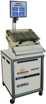
The MultiWriter pps™ on-board gang programming system uses proven, patented simultaneous programming technology to program up to 384 chips simultaneously, up to 16 different types or families — typically in seconds instead of the minutes required by conventional programmers.
Compared to other part programming solutions, MultiWriter pps delivers significant speed and cost advantages over conventional in-circuit tester-based programmers when more than four parts already mounted on circuit boards must be programmed in a single pass, making it especially effective for multi-board panels.
MultiWriter pps is optimized for applications requiring programming of at least 4 parts per board or multi-board panel. MultiWriter can simultaneously program parts on multi-board panels with 10, 20 or more boards per panel.
Advantages of On-board Part Programming with the MultiWriter pps
Product Details
The MultiWriter pps On-board Gang Programming System includes:
Purchase or Pay-Per-Use
Is Pay-Per-Use the right solution for your programmed parts?
† MultiWriter Technology is protected under U.S. Patent No. 7,802,021.
MultiWriter technology is available on CheckSum Analyst low cost in-circuit testers or in the standalone MultiWriter pps™ On-board Gang Programming System.
MultiWriter Part Programming Families
MultiWriter has a comprehensive library of supported parts families, which is being updated and expanded on an ongoing basis. The figure below shows the part manufacturers with currently supported devices in the Library. You can download an up-to-date list of supported parts by manufacturer.
Please contact CheckSum to inquire if the parts family you need is planned or currently in development.
Part Programming
The throughput of simultaneous programming with the flexibility of custom programming. MultiWriter allows unique data such as a date code or serial number for the parts to be programmed with minimal impact on programming time. The part serial number or other data such as an assembly serial number entered via bar code can be stored in a file or provided at run-time. Calibration or other measurement data can be programmed into each part separately as illustrated in the diagram below.
Smart ISP™
MultiWriter’s Smart ISP (In-System Programming) technology ensures that the ISP programming phase follows a defect-free in-circuit test of the board. The test system programs only boards that have passed the in-circuit tests. Only assemblies that have passed the opens/shorts and other component tests are powered-on. For example, if a panel has seven tested-good assemblies out of eight total, then only those seven will be powered-on for ISP device programming.
Using the Data Encryption Protection option insures your IP (Intellectual Property) is not at risk anywhere in the world. Unique data (e.g. serial number, date code, MAC address, calibration data, etc) can be written to individual chips, as they are being gang-programmed.
Board Design Considerations
As is the case in most designs, the circuit design must allow in-system programming such that the device can be programmed without the requirement to overdrive other signals. The ISP device programming pins must be accessible via a bed-of-nails fixture—just like any other in-circuit test point.
The board or multi-board panel assembly layout should provide electrical access to the programming pins that are as physically close as possible to the device being programmed in order to minimize crosstalk and noise.
Device Programming Considerations
MultiWriter allows unique data such as a date code or serial number for the parts to be programmed with minimal impact on programming time. The part serial number or other data such as an assembly serial number entered via bar code can be stored in a file or provided at run-time. Calibration or other measurement data can be programmed into each part separately. Since unique data is typically a very small portion of the overall part memory, the programming time for chip-unique data will be minimal. A standard data file format (INTEL hex, Motorola S-Record, SVF, STAPL) is used for storage of unique data that is accessed during the ISP programming process.
The MultiWriter Controller board has two operating modes: Program and Verify. In Program mode, the controller places the ISP chip in the “program” state and code appropriate to the device is retrieved from the computer memory and applied via the fixture-based buffer boards. Once chip programming is complete, the MultiWriter controller places the chip in the “read” state and the code just programmed is verified. The Program and Verify operations can occur on a Test Step basis.
The board assembly (or individual panel in a multi-up assembly) will be powered-up to program the part, so some test system power source must be available and sufficient.
* Up to 16 MultiWriter control modules with up to 24 buffer modules each for 384 maximum devices. One MultiWriter control module required for each different device type.
† MultiWriter Technology is protected under U.S. Patent No. 7,802,021.
MultiWriter On-Board Gang Part Programming
Programming CPLD (Complex Programmable Logic Device) parts such as microcontrollers, serial Flash and FPGAs after they are attached to the circuit board [’on-board programming’] simplifies the manufacturing process and reduces inventory and rework costs compared to mounting pre-programmed chips.
Since the contents of Phase Change Memory (also known as PCM, PCME, PRAM, PCRAM, and C-RAM) can be lost because of the high temperatures needed to solder the device to a board, on-board programming is required.
Simultaneous Part Programming
MultiWriter uses patented simultaneous programming technology to simultaneously program up 384 chips at one time, up to 16 different types — usually in seconds instead of the minutes required by conventional programmers.
MultiWriter technology has already programmed millions of parts on millions of boards. Its ability to program up to 384 chips at once makes MultiWriter the industry’s most productive on-board part programmer.
MultiWriter Multiplies Productivity Two Ways
MultiWriter technology is available on CheckSum Analyst low cost in circuit testers or in the new standalone MultiWriter pps™ on-board gang programming system where at least four parts need to be programmed on a board or multi-board panel.
MultiWriter installed in an Analyst series in circuit tester:

MultiWriter pps used following the traditional in circuit tester:
MultiWriter Features & Benefits
MultiWriter technology is a clean, low cost solution to increase part programming productivity–regardless of whether it’s in an Analyst in circuit tester or in the MultiWriter pps gang programming system.
MultiWriter is the first ISP programming system integrated right into the bed-of-nails fixture
Simultaneous device programming
Comprehensive device and bus algorithm library
Unique data may be programmed on a per-device basis — even on panelized boards
Fixture-mounted buffer boards ensure the highest signal quality
¹ Up to 16 MultiWriter control modules with up to 24 buffer modules each for 384 maximum devices. One MultiWriter control module required for each different device type.
† MultiWriter Technology is protected under U.S. Patent No. 7,802,021.
As CPLD memory sizes increase, fast programming times are critically important. MultiWriter delivers impressive throughput improvements over convention ICT-based part programming approaches via three key innovations:
The example multi-board panel assembly illustrated at right demonstrates how MultiWriter with simultaneous part programming multiplies throughput compared to conventional one part at a time programming.
A panel consisting of four identical boards, each with three different programmable parts (labeled A, B, C) requires 12 separate programming and verification operations using a conventional in-line part programmer.
Simultaneous programming requires only a single program/verification step that covers all twelve parts.
Each red box represents an individual programming/verification operation.
MultiWriter Simultaneous Programming:
Requires just one programming/verification step since all chips are programmed and verified in a single programming sequence.

The MultiWriter Part Programming System solves the throughput and cost problems of earlier ISP programming techniques used in-line on in-circuit testers (ICT) and with 'dongle’-based approaches used at functional test.
Using CheckSum’s patented simultaneous programming technology to program up to 384 serial parts in a single pass, MultiWriter technology makes on-board part programming practical, affordable and productive.
And fast. Serial Flash, EEPROMS, embedded microcontrollers, and FPGAs are programmed at near-data book speeds. Since the contents of Phase Change Memory (also known as PCM, PCME, PRAM, PCRAM, and C-RAM) can be lost because of the high temperatures needed to solder the device to a board, on-board programming is required.
Using the Data Encryption Protection option insures your IP (Intellectual Property) is not at risk anywhere in the world. Unique data (e.g. serial number, date code, MAC address, calibration data, etc) can be written to individual chips, as they are being gang-programmed.
A unique test fixture-based controller and buffer card architecture reduces cost, improves signal quality. A USB 2.0 bus directly from the controller to computer and MultiWriter software designed for speed complete the productivity equation.
Software architecture enables simultaneous part programming
MultiWriter’s ability to program ISP devices simultaneously rests on its patented architecture that allows it to program up to 384 serial ISP devices per board or multi-up panel at high speed.
The total programming time is identical for a single chip on a single board, one chip per board on a multiple panel assembly, or any combination in between. Device-specific code is programmed following the simultaneous programming step. Since the amount of device-specific code is small compared to the code common to all chips, total programming time is affected very little, if at all.

For example, benchmark results conducted by CheckSum show that MultiWriter can program one or five Freescale 9S12H128 microcontrollers in the same amount of time using the BDM (Background Debug Mode) bus. Programming speed is limited by the chip, while the memory size for this microcontroller is 128k, but only 64k was programmed. With MultiWriter, the software overhead, programming, and verification took a total of 12.21 seconds (0.61 seconds software overhead, 6.13 seconds programming, and 5.47 seconds verification) for one device or for five devices, or more.
MultiWriter hardware is designed for low cost and high signal speedsMultiWriter hardware consists of two elements:
The controller and as many buffer boards as required are mounted inside test bed-of-nails test fixture. This cost-effective design eliminates the requirement to modify the test system or install costly special-purpose channel cards.
Any MultiWriter-equipped fixture can be used on any CheckSum Analyst test system equipped with MultiWriter software on its PC or on the MultiWriter pps On-board Gang Programming System.
Short wire lengths between the buffer boards and the device being programmed/verified is ideal for dealing with increasing programming speeds.
MultiWriter ISP System Computer Interface
Controller Board
Buffer Board
Note: The MultiWriter ISP System is appropriate for circuit boards and multi-board panel assemblies requiring on-board code programming and verification of serial bus ISP devices. MultiWriter is available only as an integrated element of a CheckSum-developed application package that includes a bed-of-nails fixture and associated test program operating on an Analyst in-circuit test system or on the MultiWriter pps On-board Gang Programming System.
* Up to 16 MultiWriter control modules with up to 24 buffer modules each for 384 maximum devices. One MultiWriter control module required for each different device type.
† MultiWriter Technology is protected under U.S. Patent No. 7,802,021.
The MultiWriter Part Programming System solves the throughput and cost problems of earlier ISP programming techniques used in-line on in-circuit testers (ICT) and with 'dongle’-based approaches used at functional test.
Using CheckSum’s patented simultaneous programming technology to program up to 384 serial parts in a single pass, MultiWriter technology makes on-board part programming practical, affordable and productive.
And fast. Serial Flash, EEPROMS, embedded microcontrollers, and FPGAs are programmed at near-data book speeds. Since the contents of Phase Change Memory (also known as PCM, PCME, PRAM, PCRAM, and C-RAM) can be lost because of the high temperatures needed to solder the device to a board, on-board programming is required.
Using the Data Encryption Protection option insures your IP (Intellectual Property) is not at risk anywhere in the world. Unique data (e.g. serial number, date code, MAC address, calibration data, etc) can be written to individual chips, as they are being gang-programmed.
A unique test fixture-based controller and buffer card architecture reduces cost, improves signal quality. A USB 2.0 bus directly from the controller to computer and MultiWriter software designed for speed complete the productivity equation.
Software architecture enables simultaneous part programming
MultiWriter’s ability to program ISP devices simultaneously rests on its patented architecture that allows it to program up to 384 serial ISP devices per board or multi-up panel at high speed.
The total programming time is identical for a single chip on a single board, one chip per board on a multiple panel assembly, or any combination in between. Device-specific code is programmed following the simultaneous programming step. Since the amount of device-specific code is small compared to the code common to all chips, total programming time is affected very little, if at all.
For example, benchmark results conducted by CheckSum show that MultiWriter can program one or five Freescale 9S12H128 microcontrollers in the same amount of time using the BDM (Background Debug Mode) bus. Programming speed is limited by the chip, while the memory size for this microcontroller is 128k, but only 64k was programmed. With MultiWriter, the software overhead, programming, and verification took a total of 12.21 seconds (0.61 seconds software overhead, 6.13 seconds programming, and 5.47 seconds verification) for one device or for five devices, or more.
MultiWriter hardware is designed for low cost and high signal speedsMultiWriter hardware consists of two elements:
The controller and as many buffer boards as required are mounted inside test bed-of-nails test fixture. This cost-effective design eliminates the requirement to modify the test system or install costly special-purpose channel cards.
Any MultiWriter-equipped fixture can be used on any CheckSum Analyst test system equipped with MultiWriter software on its PC or on the MultiWriter pps On-board Gang Programming System.
Short wire lengths between the buffer boards and the device being programmed/verified is ideal for dealing with increasing programming speeds.
MultiWriter ISP System Computer Interface
Controller Board
Buffer Board
Note: The MultiWriter ISP System is appropriate for circuit boards and multi-board panel assemblies requiring on-board code programming and verification of serial bus ISP devices. MultiWriter is available only as an integrated element of a CheckSum-developed application package that includes a bed-of-nails fixture and associated test program operating on an Analyst in-circuit test system or on the MultiWriter pps On-board Gang Programming System.
* Up to 16 MultiWriter control modules with up to 24 buffer modules each for 384 maximum devices. One MultiWriter control module required for each different device type.
† MultiWriter Technology is protected under U.S. Patent No. 7,802,021.
Every test system installation has different requirements. That’s why CheckSum provides a long list of options and accessories that tailor the installation to fit your needs.
CheckSum test controllers are used to control the test system software and electronics. The CheckSum test system resources (modules/boards) are installed in a separate industrial chassis. You can use your existing PC or purchase one from CheckSum. If a test system is purchased with a PC controller, the test system is shipped configured, tested, and covered under a single warranty.
Since the PC industry rapidly changes, contact CheckSum about present or alternative configurations.
System PC with 20 Slot Chassis for Test System Resources
System PC Dimensions:
12.45 in. (H) x 13.40 in. (D) x 3.65 in. (W)
316mm x 340mm x 92.7mm
System PC Slots:
1 low-profile PCI
(H: 2.5 in. x L: 6.6 in.)
1 low-profile PCIe x16 graphics
(H: 2.5 in. x L: 6.6 in.)
20-Slot Chassis Dimensions:
17 in. (W) x 22 in. (D) x 7 in. (H)
432mm x 559mm x 178mm
In order to accommodate the complexities of power-on functional testing, CheckSum offers a selection of accessories. Some of these mount into controller (PC) expansion slots, while others are typically mounted in available rack space or inside the test fixture (in close proximity to the UUT connections). The fixture-mounted accessories are installed with screws through provided standoffs. Connections are made with standard ribbon-cable connectors or wire-wrapping.
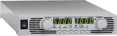
PS-UUT-L1 Programmable Power Supply
The PS-UUT-L1 programmable power supply option is used to provide UUT power for functional test and device programming with MultiWriter.
| Features | |
|
|
GPIB IEEE-488 Controller (GPIB-USB)
The GPIB IEEE-488 option allows you to connect and control external instrumentation with the CheckSum test system.
The GPIB-USB option can directly control GPIB instruments from within the CheckSum System software or you can write your own software using the included documentation. The GPIB-USB connects to an unused test system USB connector and to IEEE-488 instruments. This controller does not require a GPIB cable to connect to your instruments. You can attach it directly to the GPIB port on your instrument and then connect the USB cable to the USB port. If you have multiple instruments in a daisy-chain or star configuration, attach any cables that connect to the other instruments first, and then connect the GPIB as the last connector in the stack.
Model DIG-1 Digital I/O Module
The Model DIG-1 module can be used to power-up and functionally test circuit assemblies with digital I/O signals.
The Model DIG-1 is controlled by CheckSum’s Visual ICT/MDA™ for Windows software. This software provides a variety of software functions to create a flexible test environment. The DIG-1 digital I/O pins can also be controlled by boundary-scan.
The DIG-1 module provides 48 relay-isolated digital I/O pins and Visual ICT/MDA test systems can be configured with 96 pins per system. The module supports 3.3V and 5V logic levels. Relay-isolation allows the DIG-1 module to be used with integrated ICT/MDA and functional test fixtures.
The Model RM-1 general purpose Relay Module can be installed in an unused controller (PC) slot. It provides eight undedicated relays, four form-C and four form-A, rated at 1A. This relay module can be used for switching UUT power or signals, and also includes eight optically-isolated, high-voltage digital inputs. The Model RM-1 installs in a short PC expansion slot and has a 37-pin D-Sub back-panel connector.
50 Test Point Switch-Over Board (FIX-50P-SWO)
The FIX-50P-SWO is a 50-pole double-throw relay board normally mounted inside the fixture. It can be used to disconnect test points to eliminate loading, prevent overvoltage at the test inputs, switch test points between analog and digital signals, or to discharge the UUT prior to testing. A single TTL input signal controls all the relays. The relays are powered by a +12VDC source such as the PC’s power supply.
17 Test Point Switch-Over Board (FIX-17P-SWO)
The FIX-17P-SWO is a 17-pole double-throw relay board normally mounted inside the fixture. Relay contacts are accessed through common (COM), normally closed (NC), and normally open (NO) with each set on 17-pin headers and the relays are DPDT non-latching. This board is used to connect signals during functional test, share system resources between multiple UUTs, or provide isolation for ICT points. Works with +12V and DIG outputs from PWR-2 or FUNC-2B module.
16 Test Point Independent Relay Board (FIX-16P-IRB)
This board has independent control of 8 relays, each with 2 contacts and is normally mounted inside the fixture. It can be used to disconnect test points to eliminate loading, prevent overvoltage at the test inputs, switch test points between analog and digital signals, or to discharge the UUT prior to testing. Each of the 8 control signals activate 1 relay with 2 contacts. The relays are powered by a +5VDC source such as a system power supply. This board is used to connect signals during functional test, share system resources between multiple UUTs, or provide isolation for ICT points. Works with +5V and DIG outputs from PWR-2 or FUNC-2B module.
The Model FUNC-2 provides 16 relay-switched test points at its back panel. These test points can be expanded in 50-point increments by adding Model TR-6-1 Relay Modules (up to six TR-6-1 modules can be configured into a system).
The relay test points are used for UUT connections that exceed ± 12 volts with respect to the computer chassis when power is applied to the UUT. The Model FUNC-2 can make DMM and Counter/Timer measurements at these points. In addition, unguarded 2-wire ICT measurements (e.g. resistance, capacitance and inductance) can be made through these points. Each TR-6-1 module uses one full-length/full-height chassis slot.
TR-6-2 Fixture Interface Module
The Model TR-6-2 Fixture Interface Module provides various special functions in the test fixture. It includes two double-contact 10A power relays for switching UUT power. Optionally, it can be populated with six additional TR-6-2-RLY power relays, a dual-channel counter-timer buffer/prescaler (TR-6-2-CT), two DMM differential buffer/amplifiers (TR-6-2-DMM), and up to four 17-point switch-over modules each using two power relay sockets (TR-6-2-SWO). A breadboard area provides room for custom circuitry such as DC-DC converters. Other TR-6-2 accessories include cabling for direct connection to CheckSum’s vacuum receiver interface (50-pin is TR-6-2-THC, 17-pin is TR-6-2-SWC). All the FUNC-2 back-panel connections (relay-isolated fused power, digital and analog I/O, relay-switching) are available on the TR-6-2.
The Fixture Interface includes standoffs for easy mounting inside the fixture or on any flat surface. The 50-pin ribbon cable from the Model FUNC-2 back panel can be directly plugged into the Fixture Interface. Alternatively, when used inside a Model TR-3A vacuum test head, the special Model TR-6-2-THC plugs directly from the Fixture Interface to the inside of the fixture wiring block connected to the Model FUNC-2.
The basic Fixture Interface contains two power relays, connectors and interface circuits. You can install your own components to tailor it to your application or purchase kits from CheckSum to populate it as necessary:
The TR-6-2-SWO switch-over modules install into the power-relay sockets. Each TR-6-2-SWO, which uses two relay sockets, allows change-over of up to seventeen test points to select different source/measurement electronics or to locally isolate test points in the fixture to minimize capacitive loading on selected UUT points during power-on testing.
Boundary-Scan Partners
Asset InterTech
ASSET’s JTAG ScanWorks is a cohesive environment that delivers powerful test and on-board programming and configuration capabilities based on boundary-scan (IEEE 1149.1 JTAG) technology.
Corelis
Corelis’ ScanExpress™ Boundary-Scan (JTAG) systems offer complete solutions for prototype debug, manufacturing, and In-System Programming (ISP) of CPLDs and Flash memories. Design and test engineers can develop boundary-scan tests during the product’s development and prototype stages and then reuse the vectors in manufacturing, significantly reducing test development time and costs.
JTAG Technologies
JTAG Technologies, the world leader in IEEE 1149.1 boundary-scan applications, provides a wide range of proven solutions for JTAG testing.
![]()
Goepel Electronic
GÖPEL electronic has been among the first vendors to launch respective tools. Today we offer you the widest range of tools to benefit from the various features IEEE Std 1149.x has to offer. As a leading vendor of Intelligent Solutions for Extended JTAG/Boundary Scan, GÖPEL electronic not only provides stand-alone Boundary Scan solutions, but also is an ideal system integration partner for the combination of this technology with AOI systems, Flying Probe, Functional, and In-Circuit Testers.
CheckSum test systems can be enhanced with a variety of options and accessories that will enhance your system’s performance and convenience.
Model T-120-2U Industrial 40-Column Strip Printer
40-Column Strip Printer
The CheckSum T-120-2U Industrial Strip Printer can be used to print test results. It is compact and the 40 column print-out can be easily removed to accompany the assembly being tested. You may also want to use a standard 80-column printer with your system for printing test programs, statistical process control (SPC) reports and other files.
Model T-120-3 Foot Switch
Foot Switch
CR-2 Milli-Ohm Meter Module
The CR-2 module is used to test low-resistance components on circuit assemblies such as connectors, relay contacts, PCB traces, and shunt resistance. The CR-2 can make accurate milli-ohm resistance measurements with 2W, 200mW, and 20mWranges
CM-3 Calibration/Verification Module/Fixture
The Model CM-3 Calibration/Verification Module/Fixture provides external confirmation of the system’s calibration. The CM-3 Module/Fixture includes precise components that verify the accuracy of the Analyst series, TR-8 or TR-4 measurement systems with the included software. The CM-3 can be used for test system traceability to the National Institute of Standards and Technology (NIST). The Model CM-3 reference components can also be characterized in an external calibration lab for traceability. The CM-3 provides the traceability typically required in ISO 9000 certified sites. The unit can be purchased without traceability documentation certificate or with traceability documentation (order the Model CM-CAL).
The calibration accessory can be purchased as a separate module (Model CM-3) or integrated into a test fixture (e.g., CM-3-KIT2KN, CM-3-KIT1000 or CM-3-KIT600).
Operator’s Keypad
The Model TR-8-KEYPAD allows the operator to use the TR-8/TR-10 system without a standard keyboard. The keypad provides three system status LEDs (green for pass, red for fail, amber for busy). The keypad has eight keys for operator control. F1 through F7 keys are used for most operations such as next-test or retest, and the ESCape key aborts most operations. The keypad is connected directly to the System Module back panel.
ICT Fixture Storage System
The Model FIX-P-STORAGE is a new fixture kit storage system with built-in handles. This option replaces the four tubes and bolts used to assemble the pneumatic fixture kits for storage. This kit storage option can be used on any of the fixture kits for the TR-7 or TR-9 series pneumatic fixture systems.
AC-1 Pneumatic Controller
The Model AC-1 Pneumatic Controller is designed to allow automatic control of pneumatic air cylinders. A single TTL/CMOS signal or contact closure actuates an electric solenoid inside the AC-1 directing air from the Input port to either the Engage or Disengage output ports.
Model AC-1 Specifications:
| Line Voltage | 115/230VAC, 50/60Hz, 25VA |
| Air Switching | Dual action, 50-120PSI Quick Connect Air In, Engage and Disengage Ports |
| Manual Control | Engage, Remote or Disengage |
| Remote Control | 5V CMOS/TTL signal (pull low) or contact closure to engage air |
| Interlock Control | 5V CMOS/TTL signal (pull low) or contact closure to inhibit air |
| Air Ports | Input: 0.25 inch industrial interchange male fitting, or 0.125 inch NPT female connection Engage: 0.25 inch O.D. tubing Disengage: 0.25 inch O.D. tubing |
| Overall Size | 3.25″ W x 10.5″ D x 4.25″ H |
VC-1 Vacuum Controller
VC-1 Vacuum Controller
The Model VC-1 Vacuum Controller is designed to allow automatic control of vacuum. It is typically used to control bed-of-nails test fixturing. The VC-1 is a small, standalone unit with a switch for manual operation or it can be controlled remotely. A single TTL/CMOS signal or contact closure actuates a 3-way vacuum valve inside the VC-1 to either connect or disconnect vacuum from the test fixture.
When vacuum is disconnected, the test fixture side of the valve is vented to ambient air, allowing the fixture to quickly disengage.
VC-1 Specifications:
| Line Voltage | 115/230VAC, 50/60Hz, 25VA |
| Vacuum Switching | 3-Way: Connect vacuum and close exhaust Disconnect vacuum and open exhaust to test fixture |
| Manual Control | Engage, Remote or Disengage |
| Remote Control | 5V CMOS/TTL signal (pull low) or contact closure to engage vacuum |
| Vacuum Ports | Input has 0.75 inch NPT female connection Output has 0.75 inch NPT female connection |
| Overall Size | 6″ W x 8″ D x 5.5″ H |
DM-1 Discharge System
The CheckSum Model DM-1 Discharge System isolates and protects the MDA test system electronics from an electrically charged unit-under-test (UUT). Normally, UUTs do not become electrically charged during the manufacturing process, however, functional or system testing may leave an electrical charge on a UUT. The DM-1 will protect the test system from a UUT that may have become electrically charged with up to 250 volts. The CheckSum DM-1 also protects the test system from severe static charges on a UUT. The Model DM-1 is connected between the test fixture and the MDA test system electronics. Special internal circuitry in the DM-1 prevents the MDA electronics from being connected if a charge exists.
The CheckSum test system software can detect a charged UUT and wait for the discharge. The overvoltage charge is automatically discharged. Once the UUT voltage has been discharged to a safe level, normal testing with the MDA test system can proceed. The standard CheckSum test system multiplexer cables connect to the rear of the Model DM-1. A second test cable is provided with each 50-pin discharge module to connect to the fixture.
Installing additional discharge modules in the Discharge System is quick and easy. Each DM-1-SW plug-in card protects 50 test points in the test system. The Model DM-1 can accommodate twenty Model DM-1-SW Switch Modules. A completely configured Model DM-1 Discharge System allows isolation and protection of 1000 test points. Additional Discharge Systems can be daisy-chained for higher pin-count systems.
Model DM-1 Specifications
| Front Panel LEDs | Power-on, Discharging, Unprotected |
| Front Panel Control | Discharge, Auto (Remote), Bypass |
| Rear Panel Control | On/Off Power Switch |
| Software Control | Fixture Control (FIXCT) |
| Weight | Approximately 16 lbs. (shipping wt. approximately 20 lbs.) |
| Overall Size | 17″W x 9″D x 6.25″H |
| Capacity | 1000 Points |
| Output Cables | 36 in. |
| AC Input | 100-120VAC 50/60Hz 200-230VAC 50/60Hz |
| AC Power | 75VA maximum |


